
How to Install DLCs on your modded PlayStation 3
22nd January 2025
Best ZX Spectrum emulator. Go full screen with Spectaculator
4th February 2025
Turn a ZX Spectrum into a custom USB keyboard with the Arduino Keyboard library
A while ago I bought a ZX Spectrum case and keyboard to build a replica machine using a bare metal emulator running on a Raspberry Pi. If you want to have a look at that project then please head over to this video.
But I wasn’t completely satisfied with the outcome. The emulator was great for playing games and messing around with the computer, but it didn’t have any way to save either the state of the machine, or to save data to tape. As I wanted to have a play with basic coding on the Spectrum this would mean typing code in from scratch every time. This wasn’t useable.
So in this video I’ll be taking a different approach. I’ll be using the FUSE Spectrum emulator running on a Windows PC and rebuilding the Spectrum case into a USB keyboard so that I can use it as a normal Spectrum whilst running the emulator. All of the Speccy multi function keys will work as normal by mapping them to the relevant PC keys along with the Caps Shift and Symbol Shift keys to get the full range of keywords.
So let’s get started by looking at the hardware and software we’ll need to make the project.
Hardware
The ZX Spectrum keyboard is a membrane construction with contacts arranged in 8 rows of 5 keys. This gives the standard rubber key layout from the original machine. If you’ve got a later model like my Spectrum + you’ll have some extra keys, but these are sort of fake keys. They reproduce some useful functions from the standard layout but do so by pressing two keys at once on the keyboard.
For example pressing the Delete button is actually wired to press both the 9 key and the Caps Shift keys together.
So from a hardware perspective any Spectrum keyboard can be handled with the same 8 x 5 matrix.
If you look at a Spectrum keyboard membrane you’ll see two ribbon cables with the row and column connections. These are the raw matrix wires from the switches so we need to wire these into our control circuit correctly to make them function.
The basic idea for any keyboard is use this matrix circuit so that we can monitor many more keys than we have I/O pins. The row and column wires are arranged in horizontal and vertical tracks with switches connected across the intersections.
The column wires are held high through pull up resistors but connected to input pins on our controller. The row wires are connected to output pins which are initially held high as well. In this state pressing any key will have no effect on the state of any of our column input lines.
We can now activate a row of keys by pulling a single row wire low. Now when any key in that row is pressed it will connect its column line to zero volts pulling it down and providing a low input signal to our controller. We then turn that row off and repeat the process for all the rows in turn.
With the basic matrix we do have to consider more than one key switch being pressed at the same time. If we are scanning a row and a key is depressed it connects its column to 0V. If another key in that column is pressed it will connect the same column line to 5V. This could potentially cause a short, or at least leave our column line in some undetermined state giving a bad key press reading.
To get round this we add a diode to the row lines which blocks the 5V signal filtering back to any column lines.
Microcontroller
So we need a microcontroller that will give us 13 digital IO pins. We’re also going to need an easy way to connect it to our computer as a fully functioning USB device. This is different to just creating a simple serial port as the controller will need to identify itself as a keyboard and handle the full USB interface. The microcontroller doesn’t need to be very powerful or have much RAM or Flash storage as we have minimal data storage and the code will be relat.
I’m going to use an Arduino Pro Micro. This is a variation on the Arduino Leonardo using an ATmega32u4 microcontroller. The big advantage to this chip is that it has full USB support built in whereas the standard Arduino Uno using the ATmega328P needs some help to create a USB device.
The Arduino library also contains a keyboard and mouse driver that we can very easily use to turn the microcontroller into a full keyboard, and or mouse, with almost no configuration.
https://docs.arduino.cc/language-reference/en/functions/usb/Keyboard/
Keyboard Library
So, let’s grab a board and test out the keyboard library.
In the Arduino IDE make sure you’ve updated your libraries and board definitions. If you go to the File menu, examples, USB, keyboard and select the KeyboardSerial example you’ll get the following code.
As you can see there isn’t a lot to this to get the Arduino to send keystrokes back to the PC. We simply need to include the Keyboard library. It’s needs to be initialised in the setup function. And then we simply write key data to the keyboard to have it sent out to the PC as a key press.
If you plug in your Pro Micro board and set the IDE to use the Leonardo drivers you should be able to compile and upload the sketch to your board.
For this example if you open up the serial monitor and type a letter into the terminal you should get the next letter in the alphabet sent back to you.
If this happens we’re all set to go.
Full Circuit
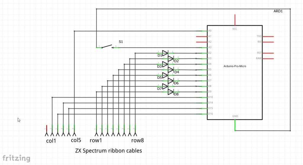
The full circuit I’ll be using is shown on screen now. Power and USB connections will be provided through the main USB-C connector. We’ll use this to both program the board and to provide the USB keyboard connection back to our PC.
After that we just need to connect the row and column signals to our IO pins and we’re all set. I’m also using an extra pushbutton to give me an extra level of control on the board if needed. On my Spectrum+ case I’ve got a handy reset pushbutton on the left hand side, but if your case doesn’t have one just wire in any switch you have.
This is the built up circuit mounted in the case. I’m using two ribbon cable connectors to capture the cables from the membrane. These can be easily found on eBay. I’m mounting them in the same place they would be on the original motherboard so as not to bend or stress the ribbon cables. They are a bit fragile, so you don’t want to bend them too much. I’m then mounting the Arduino on the bottom of my matrix board so that when I mount it on standoffs the USB connector is easily accessible through the edge connector port.
The Spectrum Keyboard Driver
As these boards are ideal for keyboard and mouse circuits there are some really great third party libraries you can use to create some very complex arrangements. I’ll leave you to have a look at those, but in this video we’ll write our own to see how everything works.
The basic idea for the code is that we will read the keyboard matrix by scanning each row. To do this we need to use the internal pullup resistors on the digital IO pins connected to the column inputs, and then run the row outputs as normal, active low driver signals.
For one scan we set all the row inputs high except for the row we are currently scanning. We then read the values of each of the column inputs. Any that are low are pressed. We can then use a lookup table to find what keycode that switch represents and then send that out to the keyboard library to send to the PC.
We then repeat the process for all the other rows, and then just repeat the whole scanning process again.
There are some additional requirements for debouncing and key presses and releases, but we’ll get to those in a second.
The final code I’m using is on screen now. I’ll stick this into a GitHub repository so you can download it. You’ll find links below and on my main project page at bytesnbits.co.uk. It’s written so that you can easily modify it to any keyboard as long as you’ve got enough pins on the Arduino to connect to.
https://github.com/getis/spectrum-usb-keyboard
Code Explanation
The way I’ve coded this is to break up the task into functional blocks.
We’ll go through the normal setup function to get the system into the running state and then use the main Arduino loop function to run the repeating scan timing. For this I’m going to run a scan every millisecond or so.
So looking from the start of the code we include the library, define our matrix size, and then a debounce timing setting.
We then define our IO pins and place them into two arrays for rows and columns. Having them in arrays will make it easy to step through the pins using simple for / next loops.
I’m also defining the input pin for the extra pushbutton before creating our keycode lookup table. This is a two dimensional array to mimic the 8 rows of 5 columns in the keyboard. By using the defined values we can make the software cope with any sized array by just changing the definitions. This avoids having magic numbers embedded in our code.
The keycode positions is taken from the Spectrum keyboard documentation which is summarised in this diagram.
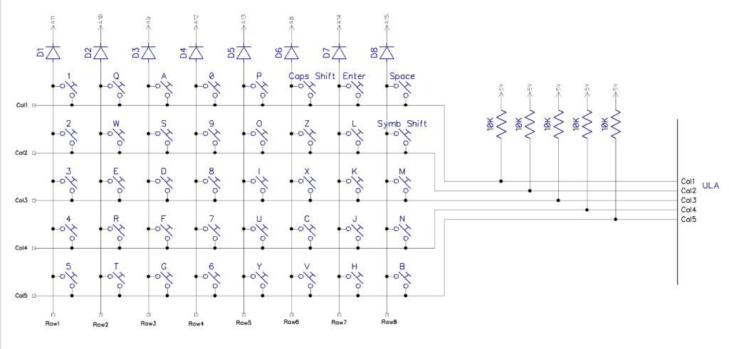
http://blog.tynemouthsoftware.co.uk/2022/05/reverse-engineering-a-zx-spectrum-keyboard.html
Most of the keys are self explanatory but the special caps shift and symbol shift need to be mapped to the keys used by FUSE to mimic those functions.
You’ll notice that our keymap simply covers the base key codes relating to each key. The shifted states and other values will all be handled by the PC with us just telling it when certain keys are pressed and then released. For example, the equals symbol is a symbol shifted L on the Spectrum keyboard. So our code will tell the PC that someone is holding down the left control key (KEY_LEFT_CTRL) and L key together.
These special key codes are defined in the Arduino Keyboard library so please check out the documentation for a full list of what’s available.
https://docs.arduino.cc/language-reference/en/functions/usb/Keyboard/keyboardModifiers/
Object Orientated Code
We now get into the main meat of the code.
I’ve modelled the task with two C++ classes. These model individual keys that are then placed into a matrix.
This first class, KeyboardKey, understands how to read a single key and then correctly send its state back to the PC.
When we instantiate or create a instance of the class we tell it its location in the matrix. It then collects the keycode from the key map and stores that for future use. It then waits to be told when to scan its key using the updateKey method.
UpdateKey assumes that the relevant row line has been activated by the Matrix Driver class. It checks the current state on the key and compares that to the currently reported state. I’m saying currently reported as we need to careful about when we detect a switch state change.
Mechanical keys, especially low quality ones as on the Spectrum, don’t give a clean connection when pressed. They bounce. So a single keypress can result in multiple ons and offs for a very short period of time. To combat this we look at the state of the key on each scan and wait for it to stabilise. Once we see the state has changed and stayed constant for a set number of scans, we then log the change and send a key action. This debounce counter does this.
The actual key data we’re sending is more basic than the full character codes from the Arduino example. We’ll be sending a signal to say when a key is first pressed down, and then a second signal when it is released. This way the PC knows which keys are being held down at any one point in time. This way it can work our when the shift and control keys are modifying a keys behaviour.
After the class definition we then create a keyHandlers array to hold our 40 KeyboardKey objects.
Next we have our MatrixDriver class. This will run the scanning process. It really has one main method, scanMatrix.
This method simply steps through each row, activating that row signal using the activateRowLine method. It then asks each KeyboardKey object on that row to scan its key before moving on to the next row.
The activateRowLine method just makes it easy to turn on a single row.
After the class definition we just create another global variable to hold the MatrixDriver object.
Setup
Next we come to the setup code. This is fairly standard apart from an initial pause state.
When we use the keyboard library it can take over the USB port. If something goes wrong in the code it can leave you locked out of the Arduino. Every time you power it on it runs your sketch, bombs out and disables the USB port. This little loop simply looks at the sate of the extra pushbutton we added and doesn’t run the rest of the code until we say so. If our code is broken this will let us back in to reprogram the device before it gets to the bad code.
After that we’re just setting up all of the IO pins and then in the for next loop we create instances on the KeyboardKey class, assign them their position and store them in the keyHandlers array. By the end of the loop we then have an 8 x 5 array of KeyboardKey objects each of which knows which key it’s responsible for.
Main Loop
Our main loop code then becomes really simple. It scans the matrix, waits for 1 millisecond and then repeats.
Circuit in Action
With the code flashed to the Arduino it’s time to test.
Using Notepad on my PC we can see that the keys are operating as normal. We’ve basically got a full set of number and letter keys along with shift and control.
If you’re getting strange characters coming through check your wiring.
Jumping on to Fuse we can now use the keyboard as it was intended. It’s still mimicking a standard PC keyboard, but the emulator is able to decode those as the proper Spectrum keys.