LaunchBox for Android – installation, game import, themes and controllers
3rd August 2023
How To Build Your 256 Full Colour LED Lightbox – DIY Project
5th September 2023Make and Code Your Own 256 Full Colour LED Lightbox – DIY Project
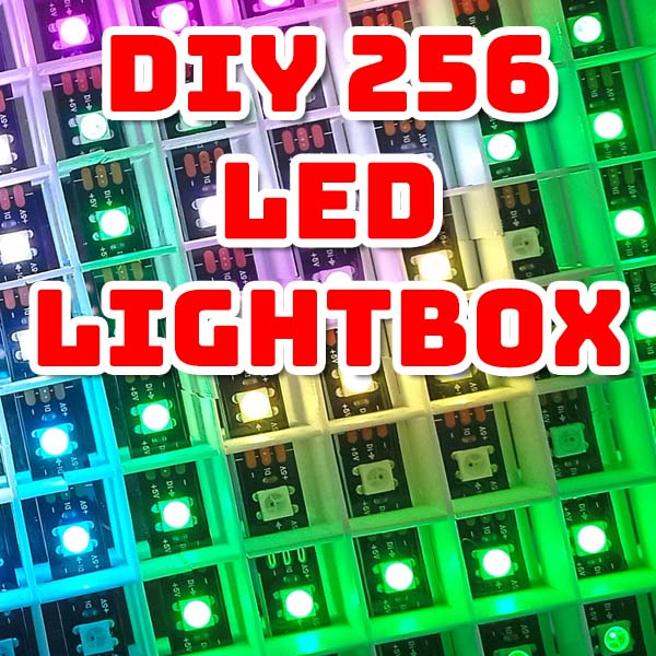
Everybody loves flashing, coloured lights and neopixels are a great way of adding full-colour, fully controlled, RGB LEDs to your microcontroller project. So what could be better than putting 256 of these together to make a computer-controlled lightbox?
In this video I’ll show you my latest Raspberry Pi Pico project where we build a 16 x 16 RGB LED matrix lightbox and program it in MicroPython so that we can create a whole range of displays and animations to brighten up our lives.
If you fancy building one of these for yourself I’ll put all the design, code and 3D printing files online for you to download and I’ll be covering the building and programming of the project in some upcoming tutorials. So please make sure that you subscribe to the channel and turn on your notifications so that you don’t miss these videos as I release them. And don’t worry if you’re not an electronics expert. If you simply want to make it I’ll provide all the software for a range of display settings that will get you up and running very easily.
But for now let’s just have a look at how this project is put together and what it can do.
Construction
The circuit for this project is really very straightforward. We got a Raspberry Pi Pico connected to a number of buttons with a single output connected to a strip of 256 neopixels. To add an extra bit of pizzazz to the project I’ve also added a microphone so that the Pico can monitor sound. At the moment I’ve just built that up using prototype board but I’ll eventually move that onto a printed circuit board, and again I’ll show you exactly how to do that in another video.
The framework for the lightbox is a mixture of 3D printer parts and cut MDF and Perspex sheets.
I’ve used an MDF baseplate to hold everything together and then 3D printed a frame to enclose the 16 x 16 LED matrix holding a semitransparent Perspex sheet about 15 mm above the LEDs. I’ve then 3D printed a divider matrix to isolate each of the neopixels so that we get each LED creating its own square pixel rather than having its light spread out and merging with its neighbours. Again all of the files and construction of this framework will be covered later.
At the back of the matrix I’ve used a mirrored Perspex sheet to push as much of the coloured light forwards and then used self-adhesive neopixel strips, cut to length and stuck down onto this mirrored sheet.
Wiring the matrix is quite simple. The single data line from the microcontroller enters the matrix in the bottom left corner and then simply snakes its way up and down the rows needing only a single connection at the end of each line of pixels. Power is connected down the left-hand side and split into four sections to reduce the current in each of the wires.
And that’s basically it apart from a bought in 5 V power supply.
What Can It Do?
In its basic form this is simply a lightbox with coloured lights. You can use it to provide illumination with the buttons allowing you to adjust the brightness and the colour of the matrix.
As we’ve got a small computer attached to it we can program it to automatically choose a colour, fade in and fade out and then simply repeat this process choosing a different colour each time.
As you can see I’ve added the control buttons to allow us to easily move between different display settings and then control those displays while watching them.
So both of these functions simply treat the LED matrix as a single coloured light source very similar to many of the lightbox as you’ll find in the shops. But the whole advantage of our design is that we have full control over each of the 256 pixels.
16 x 16 Display
The best way to think of the LED matrix is as a 16 x 16 pixel computer display. Anything you could do on a computer monitor you can do on this lightbox.
We can run simple animations such as this bouncing box demonstration. Our microcontroller is simply generating each frame and writing it to our display.
As the Raspberry Pi Pico is quite a powerful microcontroller it can handle much more complex animations. In this demo its running Conway’s Game of Life which simulates a colony of organisms that live and die depending on the number of neighbouring live cells. It requires the microprocessor to scan the grid, apply range of mathematical rules and then generate the next frame of the animation.
For the more technically minded each of these animations, and indeed all these displays, are coded as separate modules within the software. All of the menu operation and interface between the LED matrix and the microcontroller are handled by my mini operating system. Each display module simply needs to write its information to a frame buffer provided by the OS one frame at a time when instructed to do so.
Listening to Sound
As an added feature you might remember that I added a microphone input as part of the circuit. The idea here is to allow the microcontroller to sample sound. Again all the code for this is built into the operating system which will be covered in another video, but the upshot of this is that you have a frequency plot available for you to use in your animations.
You can see this in the simple spectrum analyser demo. As I play different frequencies into the microphone you get different peaks on the display.
If we play music we’ll see the frequency spectrum for that on the LED matrix, basically giving us the sorts of display you would see on a graphic equaliser.
But again as we got a full microprocessor behind the scenes we can start to do much more complex animations based on this data.
In this display setting I’m using coloured squares to represent each of the frequency bands and then using the brightness of each square to represent the intensity of the sound. The upshot of that is that you get a sort of psychedelic tunnel effect that pulses in time to the music and I have to admit I find it very easy to get mesmerised by this one.
What’s Next?
Hopefully can see that this lightbox project is designed to be expandable. You can add your own displays where your only limited by your own imagination.
I’ll also be expanding the capabilities of the project in the coming videos. One of the first expansions will be to add Wi-Fi control using your browser on your phone and then hopefully to integrate the whole project into Alexa so we can get voice control.
Watch out for the Next Tutorials
So that’s it for this overview. If you fancy having a go at this project then make sure you subscribe to the channel. I’ll be releasing build and coding videos over the coming weeks which will show you exactly how to make your own lightbox and then go on to program your own displays.
The next video will be the basic construction of the lightbox so you can get yours up and running as quickly as possible. This will include all the information you need to put everything together and get it working without going into the actual coding. That will come in the following videos.
Make It Yourself
I’ll be publishing the full build instructions along with all the files and designs in following posts. But if you want to get hold of some of the parts I’ve used check out the links below.
**IMPORTANT**
Amazon will sometimes find the wrong product in your country. The LEDs need to be 5V, WS2812 LED strips at 60 pixels per metre (300 per 16.4 feet).


