Fix, Clean, Format, Clone and manage all your USB, SDD, NVMe and Hard Drives
19th March 2025
Bad Update Software Exploit for Xbox 360 – What is it? How does it work? Is it right for you?
30th March 2025
Use a Real Commodore 64 as a USB Keyboard for the VICE emulator
A while ago I bought myself a Commodore 64 case and keyboard with a view to building a Raspberry Pi powered emulator. That project worked really well using a bare metal emulator running on a cheap Raspberry Pi Zero and if you want to get the full story then please do have a look at the project video.
But having it as a standalone system with its own dedicated Raspberry Pi and screen made it a bit awkward to use without leaving it out on my desk so I wasn’t getting as much use out of it as I wanted.
If you’ve seen a few of my other retro computer builds you’ll have seen I’ve been slowly moving to turning them into USB keyboards so that I can use them with PC based emulators, but still get the full real computer feel using the original hardware.
So with this USB keyboard setup I’ve been having great fun with my ZX Spectrum and ZX81. You simply plug the computer in over USB, boot up the emulator and you’ve got a real retro computer sitting in front of you with all the facilities of a full fat emulator.
So in this video I’ll be showing you how to turn your Commodore 64 into a USB keyboard for use with the VICE emulator.
Parts You’ll Need
First of you’re going to need some hardware.
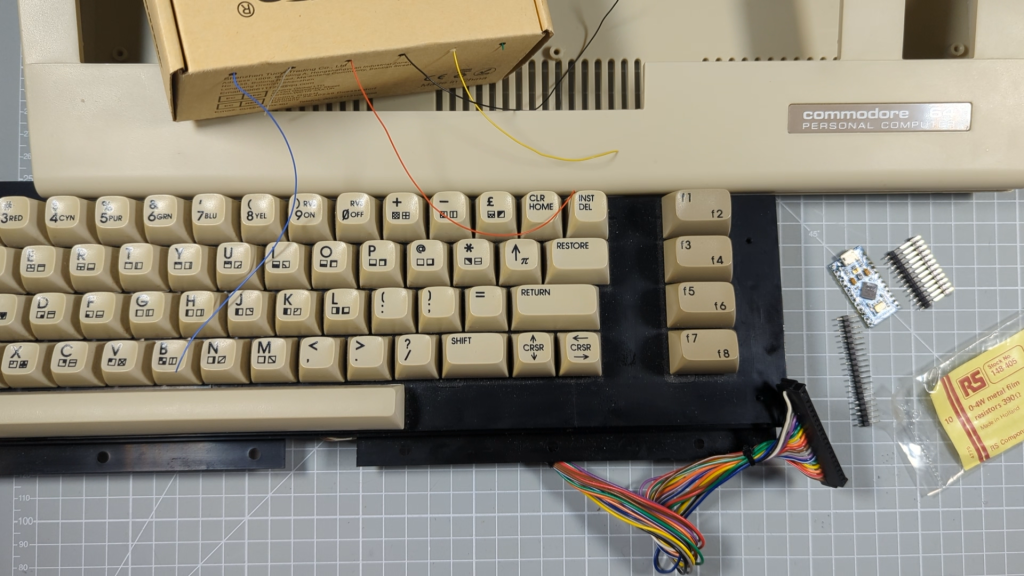
I’m using an original Commodore 64C case and keyboard. I bought these as spare parts from a really reliable UK eBay seller so that I got a fully tested and working setup. The total cost was around £50. That’s all the original parts you’ll need. I’m not hooking up original joysticks but will instead just use the PC’s USB connections for that.
The microprocessor for this project will be the Arduino Pro Micro which has just enough IO ports and supports the Arduino USB keyboard library which makes the coding of the USB interface incredibly easy.
After that you’ll need a 20pin single row header to connect to the C64 keyboard and if you want to make the power LED turn on you’ll need a 380ohm resistor. Other than that it’s just some sort of circuit board to build it on and some hookup wire, PCB standoffs and so on.
Arduino Pro Micro https://amzn.to/4hI8Spn
USB C cables https://amzn.to/4hpuqHt
Keyboard keys https://amzn.to/3ElMymY
The Circuit
The USB circuit itself is fairly straightforward. The Commodore 64 keyboard uses a standard key switch matrix with rows and columns to allow all 65 keys to be run from 18 IO pins on our microcontroller. 65 does seem a strange number for a computer but we basically have 64 keys plus the Restore key which is on its own row and column.
The first stage of working out the circuit is to identify which keys are on which rows and columns. Luckily there is a really great article at https://www.waitingforfriday.com/?p=470 where Simon Inns has already worked all of this out. His key map is shown on the screen at the moment.
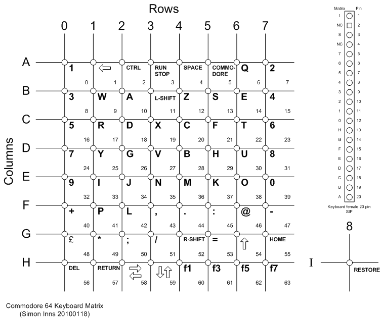
As you can see we basically have an 8×8 matrix with the restore key running from an almost separate row and column.
On the diagram you can also see the C64 keyboard connector pinout with its 20 pin header. To work out which pin is number one on the header look for a small mark at one end or look for the missing pin hole which is pin 2.
So we now need to work out how to connect these 18 IO signals to our Arduino Pro Micro.
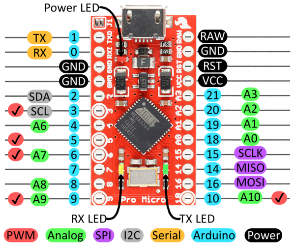
If we look at its pinout you’ll see a number of digital and other pins. The great thing about this board is that almost all of the general IO pins can be used as digital signals, with internal pullup resistors built in.
The circuit we’ll use is on the screen now. Here we are connecting all of the row signals to digital outputs on the microcontroller, but these need to go through small diodes to avoid feedback into the matrix when multiple keys are pressed.
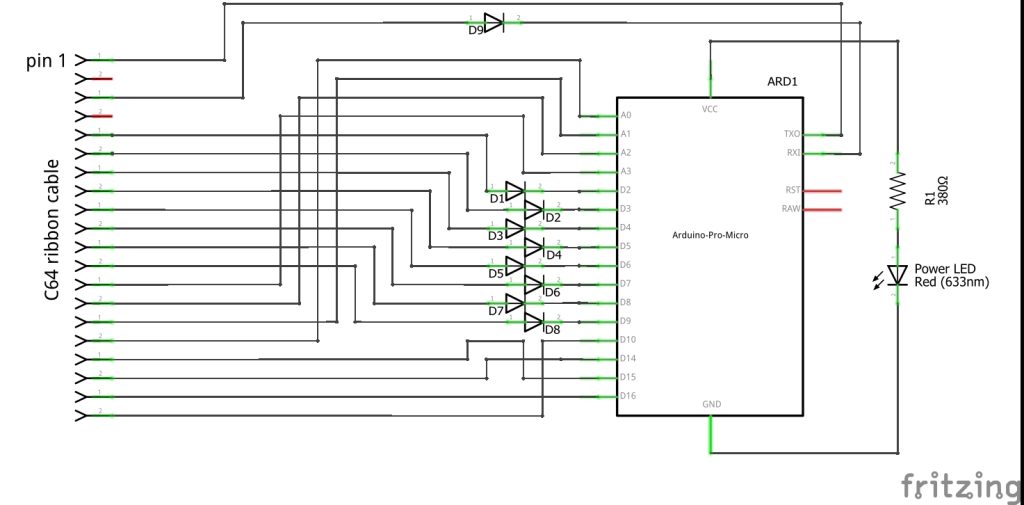
The column inputs then get connected to digital inputs but we use the Arduino’s internal pull up resistors to avoid having to add discrete components.
The basic principle is that we initially have all of the rows pins held high. The column pins will all float high through their pull up resistors. Pressing a key at this point has no effect on the circuit.
We then pull one row pin low and read the values on the column pins.
If a key on that row is being pressed it will connect the low signal on the row line to its column line pulling it low as well. If we read a low on any column we know that the key on the active row that corresponds to the low column is being pressed.
We can then set all the rows back to high and pull the next row pin low to see what keys are being pressed on that.
So our keyboard matrix circuit basically boils down to wiring the 18 keyboard lines to IO pins on the Arduino.
To get the LED on the C64 case to work we simply wire it to the Arduino VCC and GND connections through a current limiting resistor of about 390 ohms.
So here you can see my completed circuit.
I like to use this double sided matrix board for prototyping. It allows me to place my components wherever I like and then just wire them up with this thin wire wrapping wire. I find it quick and easy and very flexible.
So now we just need some software.
Keyboard Driver
The keyboard driver software is the same as I used in the ZX81 project which was first written for my ZX Spectrum video. If you want the full explanation please have a look at those. The ZX Spectrum covers the matrix driver code, the ZX81 covers the alternate key addition I needed to make for that project.
But in essence the software works like this.
First we define our IO pins and put them into arrays so that we can easily cycle through them. Next we define the button used to start the code, so row 3 column A is the RUN/STOP key. Now we set up our key matrix map. The C64 only uses the standard keys so the shifted, alternate key matrix isn’t used. The \0 values for the keys are null values so they have no effect.
As you can see in the main matrix I’ve matched the Commodore keys to the keys used by the VICE emulator. The mapping for that is shown on screen now. Basically we pick one location on the key map. Work out what key that relates to on the Commodore keyboard. Then look at the VICE keymap to work out what key we need to press on the PC keyboard to mimic the C64 key. That keycode is what we enter into the key map in our code.
The only awkward one was the equals key on the C64. This is mapped to one of the PC keys that is different for US and UK keyboards. If you look at the diagrams on screen you can see that the key three to the left of the L key is a # on my UK keyboard, but a backslash on the US version. The Arduino keyboard library sends it signals as key positions rather than characters but it’s based on the US layout. So the C64 equals button, three to the right of the L key needs to be sent as the backslash code.
Other than that all the key positions are common. If you’re using another country keyboard layout just do the same sort of thing. Work out which key position you need and send the US keyboard version.
So with our key map created we get to the main bulk of the code. I’ve used two objects to model individual keys and then the keyboard matrix.
This first object, KeyboardKey, handles a single key, monitoring its state and sending press and release signals to the PC. It also handles the key debouncing and if needed the alternate key functionality which as I mentioned isn’t used on this keyboard.
The second MatrixDriver object runs the matrix, activating each row line in turn and the asking the individual keys on that row to check their state.
At the end of the code you can see the initialisation function. This has an initial pause built into it. The keyboard library can take over the USB port. If your Arduino crashes it can lock you out of using the USB port to reprogram the board. So basically you turn the board on, it crashes and you can’t communicate with it. There are ways to reset it but it’s awkward. So the code will initially sit waiting for you to press a key on the keyboard before starting the USB section of the code. I’ve set it to the RUN/STOP button.
Finally there’s the Arduino main loop code that simply asks the MatrixDriver to scan the keyboard, waits for 1ms and then starts the next scan.
All of this code will be on my GitHub account at https://github.com/getis/c64-usb-keyboard.
So lets get this uploaded and see if it works.
Testing
Testing is simply plugging in the keyboard ribbon cable, attaching the Arduino to the PC and then uploading the sketch. If you’re not sure how to do all this please have a look at my Arduino starters guide. I’ll put a link to that in the description rather than showing it here as I’ll soon be making another version of it.
If we now turn on the serial monitor and press the RUN/STOP key we should get a message saying that the keyboard is now running.
During testing don’t worry about disconnecting your normal PC keyboard. It can cope with both at the same time.
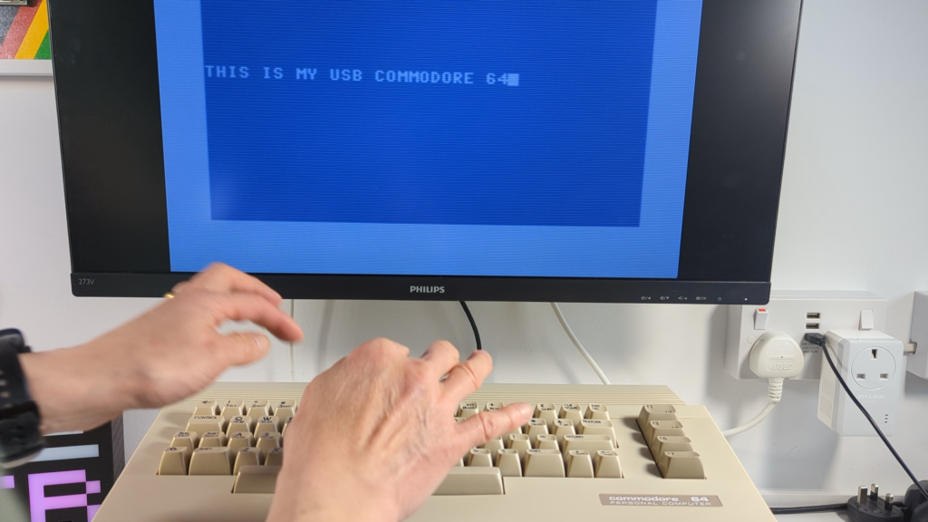
We now need to boot up VICE and drop into the Commodore 64 . We should now be able to use our real keyboard as a real C64.
Problems
If you don’t get this the most likely cause is a wiring error. There’s not a lot more that can go wrong with the circuit. Usually, you’ll see characters appearing that don’t match the keys you’ve pressed.
Conclusion
So that’s our Commodore 64 now running as a USB keyboard. Don’t forget that it’s mapped to the VICE keys so it won’t really work as a PC keyboard.
But in terms of allowing you to emulate a real C64 I think it gives a great solution and one that I find lets me get much more fun out of the system.