7in touchscreen display with sound for your Raspberry Pi or laptop
17th December 2021
Atari ST emulation on your PC – Standalone Hatari and LaunchBox integration
14th January 2022Connect an SPI LCD Display to Your Raspberry Pi Pico Using MicroPython – ILI9341 Driver
Connecting an SPI LCD display your MicroPython enabled Raspberry Pi Pico is quite a straightforward project. You only require six connections and thanks to some great micro Python libraries, driving the display is just a simple. In this tutorial I’ll show you how to connect the LCD panel, how to add the library to your project and then how to use the primitive shape and line tools to create a simple game.
So let’s get started with the actual circuit.
SPI Connections
The Raspberry Pi Pico offers a wide array of interfaces to allow you to connect to various devices. Our LCD panel uses an SPI interface so will need to use one of the two hardware SPI channels. We can use software to allow us to turn any GPIO pins into an SPI channel, but these run much slower and use up much more processing power than the hardware drivers.
If we look at the Raspberry Pi Pico pinout diagram we’ll see that the SPI0 and SPI1 interfaces can be set to use a number of different pins. So our first design decision is to decide which configuration we’re going to use for our SPI connections.
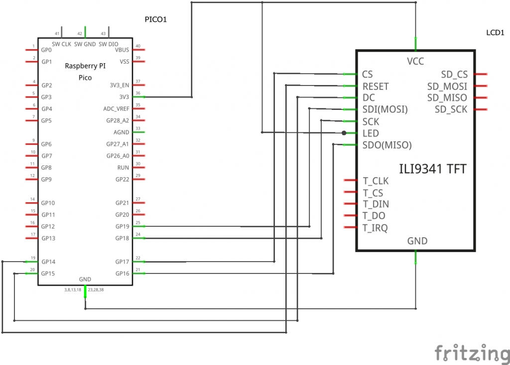
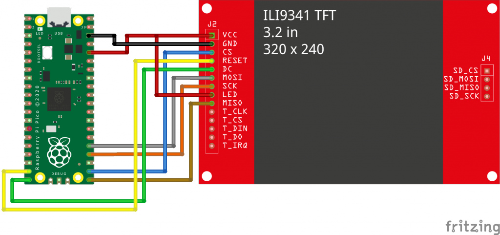
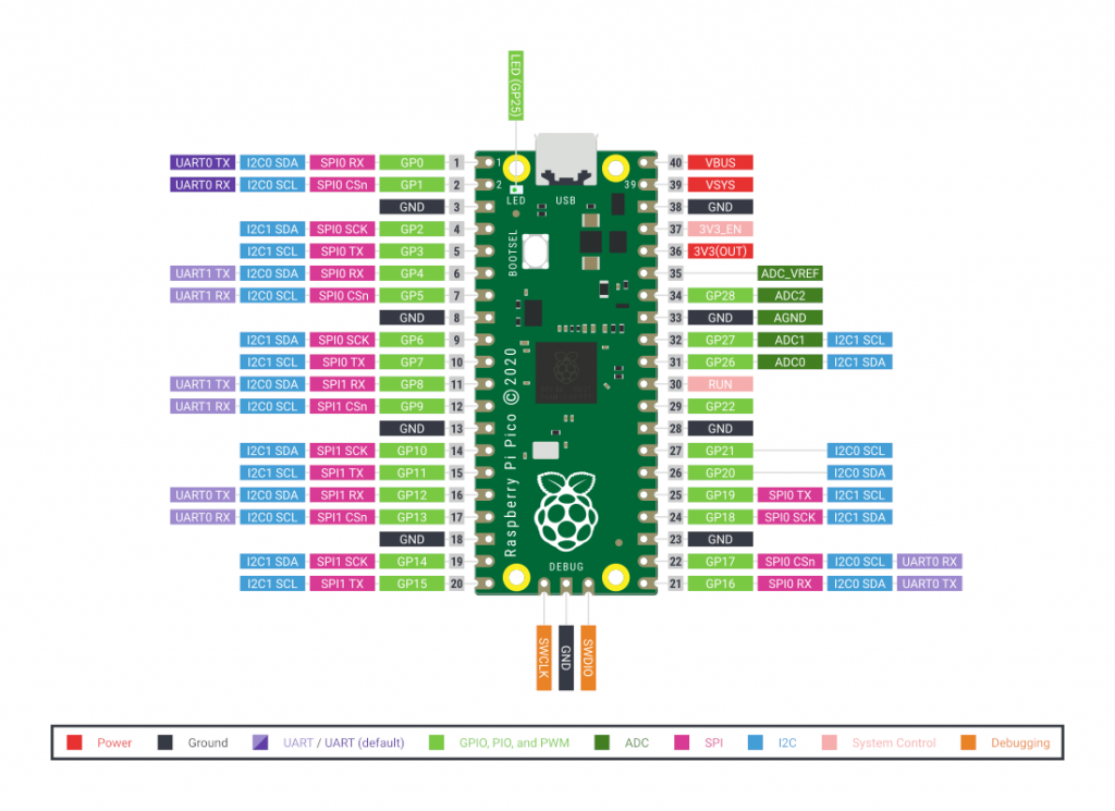 I’m going to use SPI0 connected to GP16, 17, 18 and 19.
If we then look at our LCD panel we’ll see the following connection pins that we need to connect to.
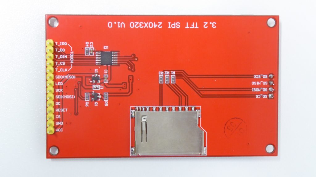
In our setup our Raspberry Pi Pico is termed the Master, and the LCD panel the Slave.
MOSI stands for Master Out Slave In. So the signal needs to connect to the data transmit (Tx) pin on the Raspberry Pi.
MISO or Master In Slave cut out, needs to connect to the data receive (Rx) pin.
SCK is the serial clock signal which will provide the pulses that move the individual bits of data.
CS is the chip select signal which allows us to tell the LCD panel when we are talking to it.
DC is the Data / Command pin which we use to tell the LCD panel if we are sending it a command instruction or actual data.
RESET allows us to send a hardware reset signal to the panel.
LED is the power supply for the screen backlight.
On top of these we obviously need to connect 0V to GND and 3.3V to VCC. We can use 5 V for a positive supply but as all the signals need to be at 3.3 V we may as well keep everything the same.
From this list of connections you’ll notice that our standard SPI connection on the Pico doesn’t include the DC and RESET pins, so I’m going to use GP15 for DC and GP14 for RESET.
So this gives us the following circuit diagram to connect the SPI LCD panel to our Raspberry Pi Pico.
 Driver Software
All we need now is a way of driving the LCD panel from our software. There are a number of MicroPython packages we can use, and I’ll actually be making a video after this one where I’ll take you through the whole process of creating your own driver package. So please make sure you subscribe to my YouTube channel so you don’t miss the next tutorials.
But the package I’m going to use for this video can be found at,
https://github.com/rdagger/micropython-ili9341
This is a really good library package which also includes a driver for the touchscreen module which I’m not going to be using at the moment.
To use the package we simply need to download the files and save them into folder on our development machine. So on the Github repository page click the green code button and then download a zip archive of all the files. Extract the files into a folder for your project and we can then open this is a new project in PyCharm.
Once you open it in PyCharm don’t forget to go to the project settings and enable MicroPython support and then let it load in the required packages. If you’re not sure how to set up PyCharm then please watch my setup video for programming your Raspberry Pi Pico.
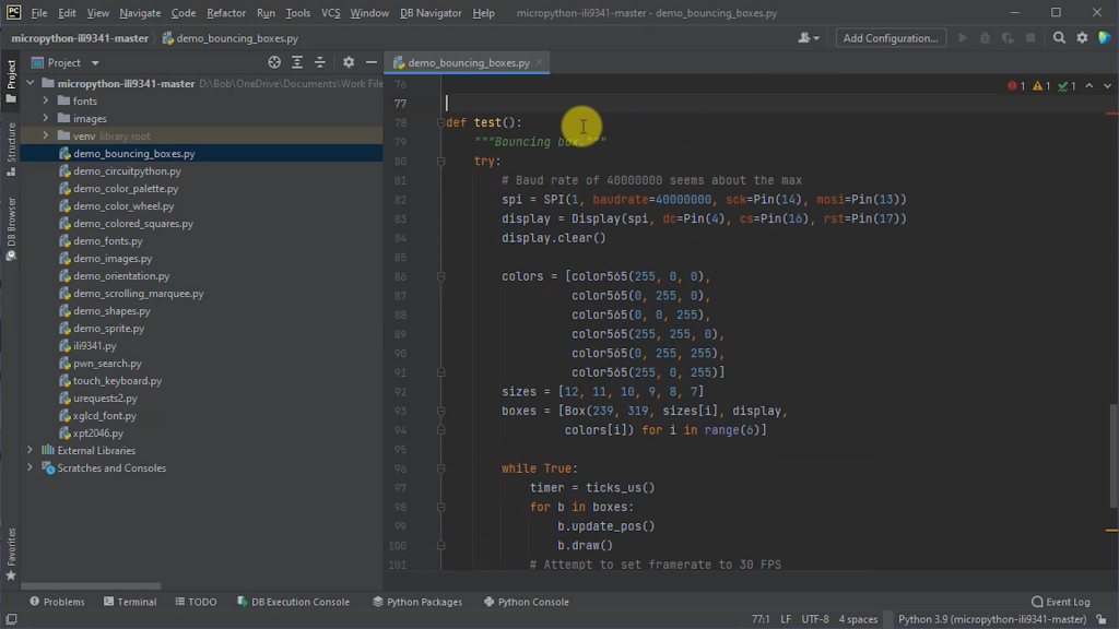
The repository contains a number of files which we don’t need for our project so we can clean up the folder to only keep the code and asset files.
Testing Our LCD Panel
A really good feature of this library is the great selection of demo programs. So we can try a couple of these to make sure that we got everything connected correctly and that our Raspberry Pi Pico is able to drive the display.
If we start with the demo_bouncing_boxes.py file we can see the code required to get the LCD panel set up and under software control.
from machine import Pin, SPI
from random import random, seed, randint
from ili9341 import Display, color565
from utime import sleep_us, ticks_cpu, ticks_us, ticks_diff
The programme starts by importing all the packages we’re going to need.
The standard machine library includes a hardware SPI driver which we need to import along with our Pin library that lets us control the GPIO pins.
We then need a few functions from the random library and the utime library, but the main one we are interested in is the ili9341 library which lets us import the Display object and the color565 function.
The ILI9341 is the driver chip used inside the LCD panel I’m using. There are a number of different ILI93xx driver chips depending on your LCD panel resolution but they all use the same basic set of commands. Indeed quite a few other manufacturer LCD driver chips use the same common command set so you should find that this driver is able to control most LCD panels.
The Display class that we are importing contains all the code to not only handle communication with the LCD panel, but also many primitive shape drawing functions that we can use to put things on the screen.
The color565 function is used to translate RGB colour values from the normal 24-bit (3 byte) resolution to a 16 bit (2 byte) resolution. Within the 16 bits we use five bits for red, six bits for green and five bits for blue.
The code mainly consists of a Box class which simply models a coloured rectangle bouncing around the screen. The important bit for us is the draw method which uses the Display class fill_hrect method to draw a coloured rectangle on the screen.
def draw(self):
    """Draw box."""
    x = int(self.x)
    y = int(self.y)
    size = self.size
    prev_x = int(self.prev_x)
    prev_y = int(self.prev_y)
    self.display.fill_hrect(prev_x - size,
                            prev_y - size,
                            size, size, 0)
    self.display.fill_hrect(x - size,
                            y - size,
                            size, size, self.color)
You’ll see that this draw method draws two rectangles one after the other. Anything withdrawn the screen will stay on the screen until we remove it. To animate a rectangle moving we have to first remove the previous rendering of the rectangle, which is the first fill_hrect call, using the background colour black and then draw the rectangle the new position in its proper colour.
The test() procedure is the main entry point that contains the programme loop. It starts by setting up the SPI interface using the built-in SPI library.
The code contained in the display driver library example is designed for a different circuit board so we need to modify this to get it to work on the Raspberry Pi Pico. The constructor function for the SPI class takes number of parameters.
spi = SPI(0,
          baudrate=10000000,
          polarity=1,
          phase=1,
          bits=8,
          firstbit=SPI.MSB,
          sck=Pin(18),
          mosi=Pin(19),
          miso=Pin(16))
display = Display(spi, dc=Pin(15), cs=Pin(17), rst=Pin(14))
The first parameter is the SPI channel we want to use and as we saw earlier I’m planning on using channel 0.
The next parameter sets the baud rate for our SPI interface. This value is in hertz so will start with a 10 MHz clock signal that is well within the operating specification for both the Pico and the LCD screen.
The next parameter is the polarity which tells the SPI channel what voltage level to set the clock signal to when we’re not sending data. Usually this will be high.
The phase parameter is next which tells the SPI channel to sample the data on either the first (0) or second (1) edge of the clock signal.
The bits parameter sets the number of bits per data value and the firstbit parameter tells the interface in which order multiple byte data should be sent. Our LCD panel expects the data to be sent in big-endian format with the most significant byte sent first.
After that we tell the SPI channel which GP pins we are going to be using for the clock, mosi and miso signals. If you have a look at the example code you’ll see that the author doesn’t specify a miso pin. In this demo we are never sending data from the LCD panel to the Pico so this signal isn’t really needed.
Once we got the SPI channel initialised the code them instantiates an object of the Display class supplying it with a reference to our SPI channel and then telling it which pins we are using for the other data signals.
colors = [color565(255, 0, 0),
          color565(0, 255, 0),
          color565(0, 0, 255),
          color565(255, 255, 0),
          color565(0, 255, 255),
          color565(255, 0, 255)]
sizes = [12, 11, 10, 9, 8, 7]
boxes = [Box(239, 319, sizes[i], display,
             colors[i]) for i in range(6)]
We then define an array of available colours using the colour565 function to convert RGB values into 16 bit values the screen understands, an array of box sizes and then an array of box objects which will be animated on screen.
The main programme loop simply moves each of the boxes calling its draw method to display the animation and then has a short delay to keep the code running at 30 frames per second.
while True:
    timer = ticks_us()
    for b in boxes:
        b.update_pos()
        b.draw()
    # Attempt to set framerate to 30 FPS
    timer_dif = 33333 - ticks_diff(ticks_us(), timer)
    if timer_dif > 0:
        sleep_us(timer_dif)
Uploading the Demo Code
So we’ve now got everything in place to give the panel a test.
If we look at the project structure we can see that we’re now using a number of different files, some of which might be contained within separate folders. To get the software to run we need to make sure that all the files used by our code are uploaded to the Raspberry Pi Pico. We can either do this manually, copying each file one by one, or we can tell PyCharm how we’ve structured our project and get it to do everything for us.
If you go to the file menu and open the project settings, underneath the project drop down you’ll see the Project Structure option. Clicking on that will bring up a list of the folders used by your code.
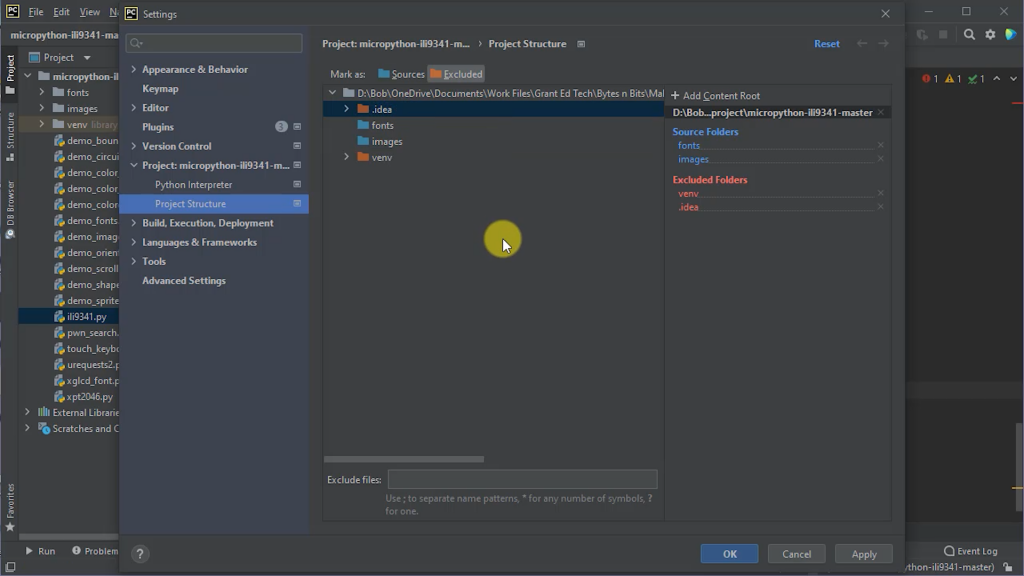
On the right hand side you’ll see the main list detailing the project root folder and then any source folders and excluded folders. At the moment the venv folder is marked as excluded as this contains the virtual environment used by the project when running on the main PC. The fonts and images folders contain source code and assets that are used by other demos in the main LCD driver package. If you right click on one of these you can mark it as a source folder so that PyCharm knows that the files in this folder need to be transferred to the Pico. If you then do this for the other folder we’ve got our project set up to allow PyCharm to manage our project uploading.
If you apply those changes and then go back to your project we should be able to right click on our project root folder and then flash the entire project to our Raspberry Pi Pico.
As we’re flashing the entire project in one go this may take a while as there are a few bitmap images in the images folder. Once we got everything uploaded will only need to update any files that we change which will make the whole process a lot faster.
Running the Demo Code
Once all of the files have been uploaded to the Raspberry Pi Pico we need to tell it to run the bouncing box demo. By default the Pico will try to run the main.py file in your project. Because we don’t have one it will just sit there doing nothing. To run the code we need to log onto the REPL interface for the Pico and start the demo code manually.
The REPL interface is basically a console app that runs on the Raspberry Pi Pico. It lets you talk directly to the MicroPython operating system so we can see what’s happening on the Pico as well as asking it to perform various operations for us.
In PyCharm you need to go to the tools menu, MicroPython and then select the REPL link. This will start the Python console and leave you with a prompt where we can type commands.
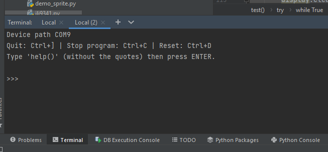
To get the code to run we simply need to import the file into our runtime environment and the demo will start to run. So type
import demo_bouncing_box
on the screen should be up and start showing boxes bouncing around the screen.
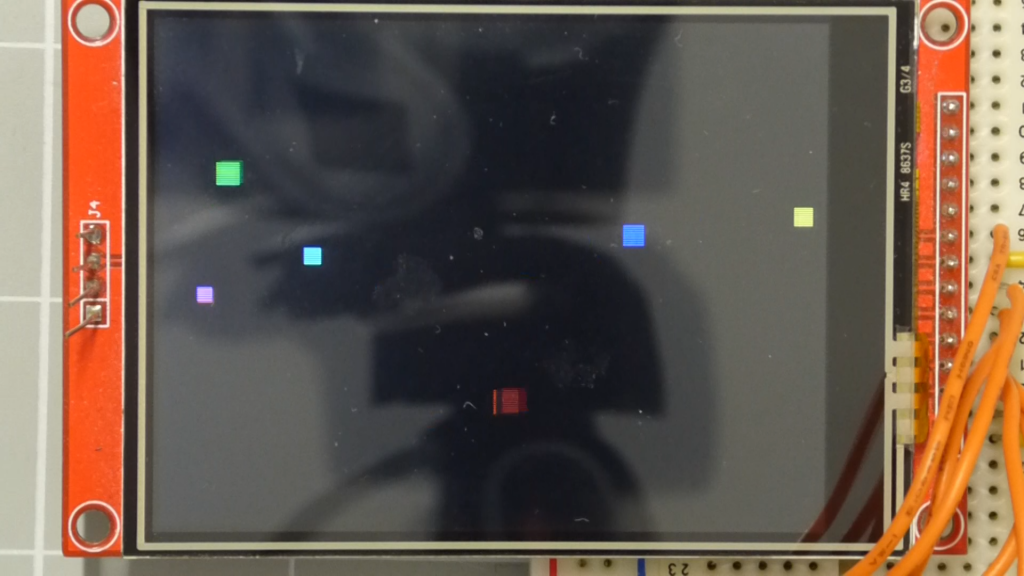
If everything is working, great! If not check your wiring and that you got the correct pins defined in the demo code. If you do need to make any changes to the code make sure you read upload any files you changed and then try running the code again.
When using the REPL console in PyCharm you must close that window before you can upload any other files. The basic rule is that you can only have one communication link with your Pico open at any one time. You’ll also find that the backspace key but strange control characters in the console. It’s actually deleting characters but unfortunately for every character it deletes it displays a couple of extra ones. They’re not actually typed in but it does make it hard to see what you currently got typed into the console. The easiest way if you make a mistake is to backspace the whole line or press return and then try again.
Using the Library Code
The LCD driver library has most of the basic drawing functions that you’ll need to build your project. These include rectangles, lines, circles, text and bitmap images. Each of these functions is demonstrated in one of the demo programs so have a look through those to see how each of them works. You can also look through the actual library source code to see how each of these functions has been implemented.
If you do want to run the other demos don’t forget to update the SPI class constructor call parameters to the Raspberry Pi Pico version. You should then be able to upload that demo file and start it from the REPL command line. If you use one of the image based demos you should already have the image folder uploaded, but if nothing shows make sure those files are added to the Pico.
Conclusion
So that should give you enough information to get your SPI LCD screen attached your Raspberry Pi Pico so that you can create some great user interfaces or start coding some games.
There are however a number of drawbacks to the way in which the system works.
When you draw objects on screen you need to overwrite them to change them. This involves blanking out the current image before you draw the new one. Each of these drawing operations needs the Pico to communicate with the LCD screen to send the data across.
Because we’re using a serial SPI channel any data transfers will be limited by the baud rate of this interface. As we saw in the constructor function for the SPI object we can set the baud rate, but the maximum the Raspberry Pi Pico can manage is 31 MHz. Although this is a fast transmission rate when we have a lot of larger objects being animated on the screen it can cause the whole system to slow down, especially as the processor core has to wait for the SPI channel data to be sent before it can continue with your application code.
So my next tutorial will start to look at how we can optimise this code to create a bitmapped display that uses a frame buffer to allow us to use frame by frame animation techniques rather than this overdraw technique. So please make sure you subscribe to my YouTube channel to get hold of that video as soon as I publish it.

