Batocera Full Installation to Portable USB and Hard Drive
10th November 2023
Bare Metal Emulation of the ZX Spectrum With ZXBaremulator
24th November 2023How to Make a Replica Commodore 64
In a recent video I used a bare metal emulator to create a Commodore 64 using a Raspberry Pi. A bare metal emulator basically does away with the need to boot into Linux, running the emulator as a native application directly on the Raspberry Pi hardware. This gives you a very fast boot time (4-5 seconds), booting straight into the Commodore 64 basic interface.
At the time I mentioned that this setup would be ideal for creating a replica computer using some real hardware. That’s what we’ll be doing in this video!
Parts You’ll Need
The main components you’ll need are a real Commodore 64 keyboard and case and a Raspberry Pi Zero 2W. You can use any Raspberry Pi up to the Pi 3B+ or Zero 2W, but not the PI4 or Pi5. I use the Pi Zero 2W as it gives me the same performance as the Pi3B+ but in a much cheaper and neater package along with the main advantage of having all the external ports on the same side of the circuit board.
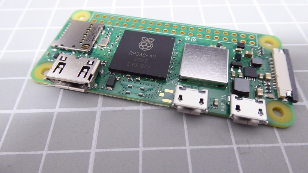
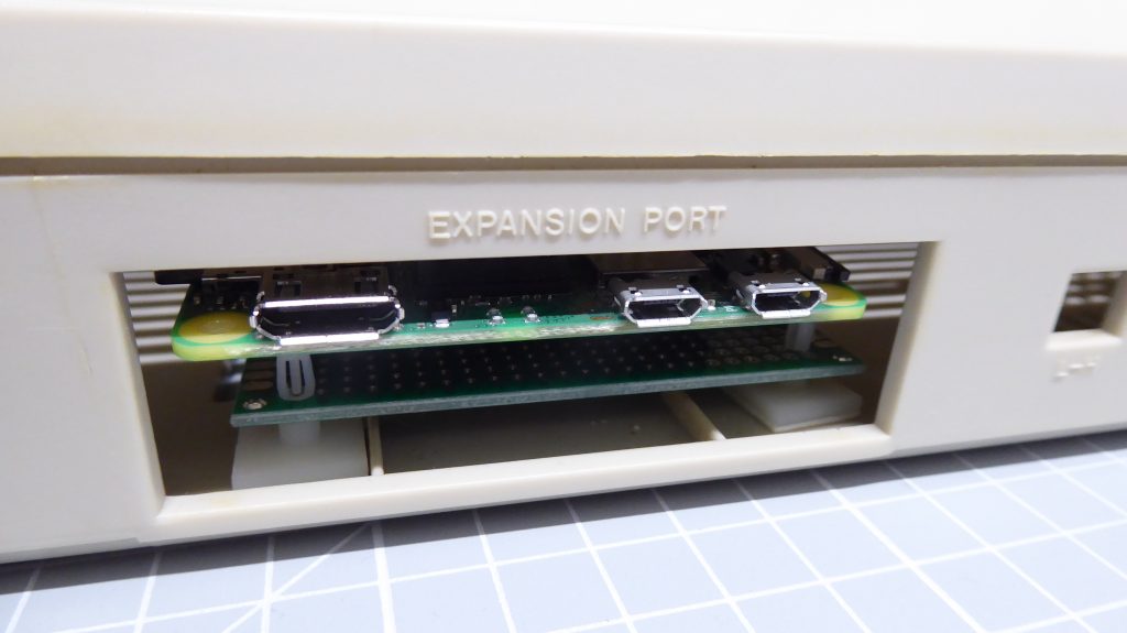
This makes it ideal for mounting into a cutout on the back of the Commodore 64 case.
As well as these main components you’ll need a 20 x 2 pin header, a 20 x 2 female PCB header, a 20 x 1 pin header, a 3 x 1 pin header, a single 390ohm resistor and some prototyping board.
Where to Get Your Commodore Parts
There are a few places that sell newly made Commodore parts but the best place to look is on eBay. There are always original Commodore 64’s for sale. For this project we don’t need a working one, or any of the power supply, tape drives or anything else. Just make sure that your case and keyboard are all in good, working order.
There are a few people who specialise in reclaiming retro computer parts. These are a great source as they will have cleaned up the cases and tested the keyboards so you can be sure of getting good quality components. I bought mine from a UK seller,
https://www.ebay.co.uk/usr/phil6581
If you do opt for a complete machine and you find some keys are not working, don’t worry, people like Phil also sell replacement components right down to the key switches and springs!
Putting It All Together
The basic circuit for the project is quite simple.
The Commodore 64 keyboard cable is terminated in the 20 pin female header. These connections are to the rows and columns of the keyboard switch matrix. They simple need to be connected to the correct pins on the Raspberry Pi GPIO header. These connections are defined in the BMC64 (the bare metal emulator we’re using) documentation.
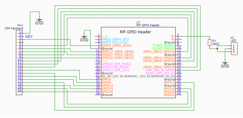
There is also a 3 pin lead for the power LED attached to the top of the case. This simply needs a current limited 5V supply which we can provide via a 3 pin header on our circuit board.
Keeping It Simple
There are a number of solutions to building this project where you can add joystick ports, external power supply connections and embed USB hubs and so on inside the Commodore 64 case. I’m proposing a very simple soultion.
We will use the internal circuit board we’ll be making to connect the keyboard directly to the Raspberry Pi Zero 2W. This will then be mounted so its ports are sticking out of the expansion port on the back of the machine. We can then connect power, joysticks and the HDMI cable directly to the Pi without needing any other components or adapters.
This lets us build the project using simple prototyping board, taking only an hour or so to complete the project!
Building the Circuit
Please see the video for full details of how I make my circuits using matrix board and wire wrapping hookup wire. A great way to get compact, working circuits very fast!
The main gotcha on the circuit is getting the GPIO header mounted so that the Raspberry Pi ports are sticking out of the expansion port. Mount it the wrong way round and you’ll not be able to plug any cables in. You have been warned!
The Finished Project
Once you’ve built the circuit you just need to mount it into the case. I use some adhesive PCB mounting feet and just stick the Pi in the right place. No need to drill or modify the case so we can keep everything in one piece!
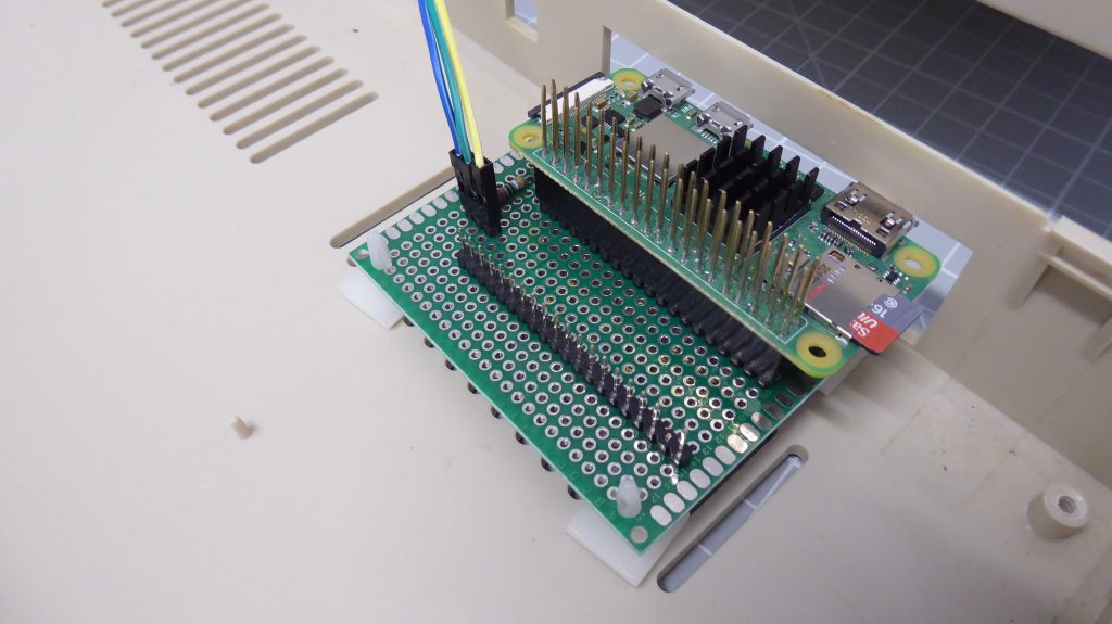
You now need to connect the keyboard cable and LED leads, close up the case and you’re done!
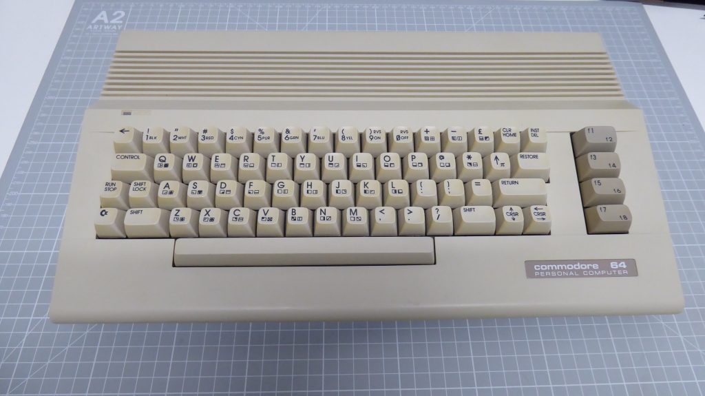
A Suitable Display
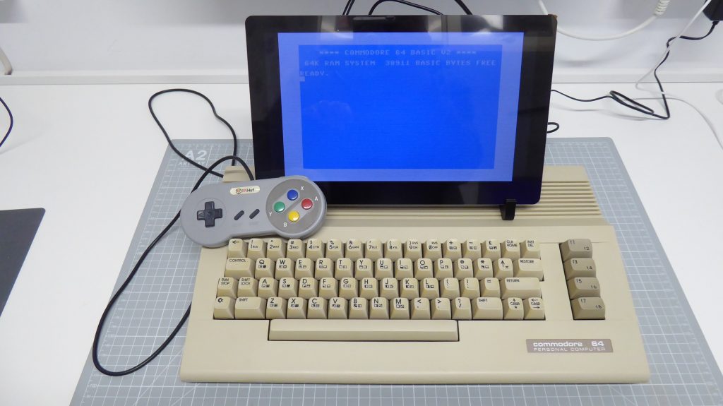
Back in the day most people used a small monitor balanced on top (or just behind) the computer. I find a small HDMI screen ideal for this.
Parts
Commodore 64 on eBay : https://ebay.us/EobqoN
Phil6581 eBay store : https://www.ebay.co.uk/usr/phil6581
Spare parts : https://www.retroleum.co.uk/
Screen : https://amzn.to/47A0GlZ
or the one I’m using
https://www.crowdsupply.com/elecrow/crowvision
Matrix prototype board : https://amzn.to/49seoZX
Male pin headers : https://amzn.to/47b1Lkr
Female headers : https://amzn.to/47rXUiy
Raspberry Pi Zero 2W : https://amzn.to/3FXfGhZ
390R resistor : https://amzn.to/47bwRYY
Adhesive PCB standoffs : https://amzn.to/471jR8l
30AWG solid core hookup wire : https://amzn.to/40yJjja
EasyEDA files : replica_c64

