
Can you buy a premium quality budget smartwatch for $40? – Tozo S7
13th February 2025
Get the full home computer experience with the Retro Virtual Machine emulator
18th February 2025
3D print your own ZX81 and turn it into a USB keyboard for emulation
The Sinclair ZX81 will always hold a special place in my heart. In May 1982 I had finally saved up 50% of the cost price of £70. My dad had said that he would match me pound for pound for my birthday so I was finally able to buy a postal order and send of for one of these amazing machines.
When it duly arrived a few weeks later my path into electronics and computers was firmly fixed.
Fast forward to today and I began thinking that it would be great to have a play around with one of these machines. Not just on an emulator, but with a real ZX81 to get the full experience of using the machine as it was intended.
Fortunately reality hit and I decided that although it would be a great project to set up a ZX81 system, for me, it would be something I only used occasionally for a bit of fun. So the emulation route seemed the best way to go, avoiding old electronics, UHF TV sets and the like.
If you’ve been following my channel you’ll have already seen my project to turn a real ZX Spectrum into a USB keyboard to use with emulators. So why not do the same for a ZX81.
Make Your Own
Looking around on eBay for a case and keyboard didn’t really turn up much under £50. Even those, looked a bit worse for wear so I’d end up having to replace the keyboard membrane and touch up the case.
But what if I could make my own case. I’d just need to add the keyboard and Arduino circuit and I’d have the project working for around £20.
My trusty Wanhao I3 Duplicator had just enough room on its printer bed to cope with the case. There was a great looking two part model available on Thingiverse. So I was ready to go.
In this video I’ll show you all the steps to getting to my finished, built from scratch, sort of ZX81.
The 3D Model
As I mentioned just now the project relies on the skills of a talented 3D modeller, Sagittario. If you pop over to their Thingyverse account you’ll find the ZX81 case project ready for download.
https://www.thingiverse.com/thing:4525078
The base of the case is fairly straightforward to print, but the top comes in two flavours.
Because the top half of the ZX81 case is awkwardly shaped printing it flat requires the top surface to be supported from underneath. That’s a lot of support material and a lot of cleaning up to do. So the designed also created a vertical print model that would print with no support required. I thought I’d give this one a go.
For this I used a wide brim for good bed adhesion to try to limit the wobble as the print got taller. So off it went.
As you can see the overall result was pretty good. But the flat surfaces weren’t very flat. Especially the area where the keyboard would sit. I felt this was just wasn’t going to give a reliable bed for the already dodgy membrane keyboard. Plus I’d printed the top in my standard PLA filament which gave a very shiny sheen that I didn’t like on this project.
So armed with a matt black filament and the flat printing model I reprinted the case top and this is what came out. Unfortunately I totally forgot to film this before I built up the project so please take my word for it that the keyboard bed came out much better and the keyboard feels nice and secure now it’s in place.
Overall print quality is OK. I haven’t felt the need to sand and polish this and I’m sure newer 3D printers will give a much better finish. So this will be my finished case.
Keyboard Membrane
With a suitable case the only other main ZX81 part is the actual keyboard. This is a membrane style design which is basically a number of sheets of thin plastic sandwiched together with printed circuit tracks held slightly apart. When you press a key area you bend the tracks until they touch giving the button press. It was a great cost saving exercise back in the day, but as for the feel of the keys….
To source a keyboard I didn’t want to buy a second hand one. After forty years I didn’t feel that was going to be a good option. Luckily there is a great supplier of brand new, re-engineered Sinclair parts, ZX Renew. I used them for my ZX Spectrum membrane and they actually supply brand new ZX81 keyboards for only £13 plus postage. If you’re based outside the UK I think they will also ship internationally.
The USB Circuit
So now on to the Arduino part of the project. As I mentioned this is going to be a rework of the ZX Spectrum circuit for this video.
The circuit and code was designed to interface with any keyboard matrix so we just need to work out the connections and mapping and it should all fall into place.
First off we need to work out the circuit used for the matrix. Looking online you can find a number of ZX81 circuit diagrams but they don’t tend to show the pins on the membrane ribbon cables. So let’s try to work these out with our multimeter.
From the diagrams we know that the 8 way ribbon cable runs the rows and the 5 way the columns. To be honest this is exactly the same as the ZX Spectrum with its forty key layout so the chances are we’re looking at the same circuit.
The matrix works by crossing rows and columns with the key switches forming connections between a single row and column. If the try to get the Q key going this should be row 1 column 1. So lets try the left most connection on each ribbon cable.
So that’s not the one, but if we trach across that row we do hit the right button on the T key.
So hopefully we’re connected to row 1 column 5.
If I now switch to what should be row 2 column 5 we can see that we’ve got the G key.
We can then go on checking the matrix to get the overall layout which I’ve summarised in this spreadsheet.
This is basically the same as the ZX Spectrum with just a couple of rows swapped around. For the ribbon cables looking in this direction, I’m marking the row and column numbers as shown. So row 1 and column 1 are side by side in the middle.
Now that we know which connection is which we can complete our circuit diagram, basically using the exact circuit from the Spectrum project.
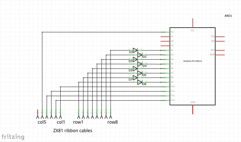
Note that we need to include a small signal diode on each row line to block feedback from one row to another. Again all of the theory of this is covered in the Spectrum video.
So all that’s left now is to build up the circuit.
I’m using double sided matrix board so that I can mount components on both sides of the board. The Arduino sticks up a bit too much at the back in the edge connector slot to mount above the board when on my standoffs, but is just right underneath. But the ribbon cable connectors need to go on top. So I’m wiring it all together with this wire wrapping wire which gives us a finished circuit like this.
So all that’s left is to mount it in the case and plug in the membrane ribbon cables.
Programming
The Arduino code is an expansion of the ZX Spectrum USB keyboard code.
First we need to alter the keyboard matrix lookup table. The actual row and column pin assignments are all the same but a few of the key positions in the matrix have changed.
The big change is caused by the way my chosen ZX81 emulator handles the keyboard. On the ZX81 the full stop or period key has the comma as its shifted state. On a normal keyboard a shifted full stop is the > symbol. In the EightyOne emulator that I’m using it uses the PC key assignments for comma and full stop. So we need our keyboard handler to notice we’re typing in a shifted full stop, but instead of sending that it needs to press the comma key instead.
To do this I’ve added a second key matrix to the code. This defines the buttons that any key should send if it’s pressed with the shift key down. You’ll see it’s mostly filled with \0 characters which denotes the null character. I’m using this code to signify that the shifted key press will be the same physical key as normal. Only the full stop key has a shifted alternative which I’ve set as the comma key.
In the update method we now pass in a reference to the shift key object so that the key can check the state of the shift key. When it detected itself being pressed it first checks if it has a shifted alternative and if the shift key is currently pressed. If not then is presses its normal key, otherwise it first releases the shift key and then presses its shifted key.
In this way we can now use this code to handle emulators that don’t exactly match the real machine keyboard functions.
One other change is that on the Spectrum I used a separate pushbutton for extra control at startup. In this version I’m going to use one of the keyboard keys. So at startup we just scan a single key and wait for it to be pressed before we take over the USB port and run the keyboard scans.
With the code completed we just need to upload it to the Arduino.
Download the Arduino code at
https://github.com/getis/zx81-keyboard
Testing
So that’s the circuit all ready for testing. If I start up the keyboard by pressing the NewLine button we should now be able to use it to type like a normal PC keyboard.
If we now boot up a ZX81 emulator we should have a fully working ZX81.