Retro Gaming – Emulation or Real Hardware – Which is Best?
26th October 2021
Raspberry Pi Zero 2 W Overview and Emulation Performance Boost – Retropie on the Pi Zero 2
1st November 2021Measure Movement on your Arduino with a Mouse – How to connect a USB / PS/2 mouse to an Arduino.
Connecting a mouse to your Arduino might seem like an odd thing to do, especially if you have no screen attached, but it can actually be used as a very accurate motion sensor. As the mouse moves over a surface it measures the distance moved in two axes which can then be read by the Arduino.
For example mounting a mouse sensor on the bottom of your robot will instantly give you movement feedback as it moves over a surface. You can then work out how far your robot has moved, and how fast it’s moving.
The ultimate aim for my project is to use the mouse to measure the rotation of a moving disc. I’ll then use this to build a spinner control for an arcade machine game controller. Usually you would use an incremental encoder attached to the spinner but these can be expensive and harder to interface to.

So let’s have a look at how a mouse works and how we can connect to it and read the data on our Arduino.
How Optical Mice Work
Most of the wired mice you can buy these days use a USB interface. Whilst we can connect to this directly using an Arduino it’s quite a complex data protocol. We are going to use a much simpler, secondary protocol that is still built into almost all modern mice. This is the PS/2 mouse protocol.
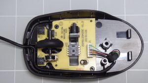
For this project I bought a very cheap, wired, USB mouse from the Amazon basics range. If you open the mouse up, don’t forget there is a retaining screw hidden under the mouse label, you’ll find that there is very little inside it. There are a few buttons, a scroll wheel with a rotary encoder attached, and the mouse motion sensor chip with its lens assembly and LED. The sensor chip is then connected to the two data lines in the USB cable along with power and ground.

The mouse sensor in this device is the PAW3515-DR-VJZA. If we look at the datasheet for this device we’ll see that it is a USB optical mouse sensor and that the VJZA variant provides both the USB interface and the PS/2 interface. If we look at the pin descriptions will see the two data pins that we will be connecting to. For USB these data pins provide the D+ and D- differential signals, but for PS/2 we will be using the CLK and DATA signals. When our Arduino connects to the mouse we will be able to put it into PS/2 mode so that we can read the motion data.
Optical mice sensors work by using a small camera which looks at the surface the mouse is running over. This is why they need an LED to provide light for the camera. As the mouse moves the camera takes images of the surface and then tries to work out how far the surface has shifted between successive images. The sensor chip also monitors the state of the mouse buttons and scroll wheel and then packages this up into a data packet that we can read over the PS/2 connection.
So now that we know how the mouse works and what data connections we need to make we need to work out how to interface our Arduino with the PS/2 connections.
Connecting the Mouse to Your Arduino
The USB cable has four cores. We can either use a USB connector to simply plug into the USB cable or you can cut the cable to access the signal wires. If you’re using a USB connector the pinout is as shown on the screen now. 5 V and ground are on the outer pins with the D+, which will be our CLK signal, and D- which will be our DATA signal as the two inner connections.
On our Arduino circuit we simply need to provide 5 V power and then connect the two data wires to two digital I/O pins. As you can see the interface circuit is incredibly simple. All the clever stuff is going to take place in software.
Coding the Interface
The PS/2 protocol is fairly straightforward to code. I’ll cover the details of this in a separate video so please keep an eye out for that if you’re interested in seeing how it all works. And don’t forget to subscribe to my channel and turn on your notifications to make sure that you don’t miss my videos as I produce them.
To make things simple I’ve created a PS/2 mouse library but you can install into your Arduino IDE. This is based on an original library by Kristopher which you can find at
https://github.com/kristopher/PS2-Mouse-Arduino
My mouse library expands upon this to add support for the scroll wheel along with fixing a few issues I found with the power up sequence and the general PS/2 interface. I’ve also added some methods to make it easier to get the movement data and button states without having to mess around with the PS/2 data package format.
You can download my library from my GitHub repository at
https://github.com/getis/Arduino-PS2-Mouse-Handler
To install this click on the green Code button and select the download option. This will download the library as a zip file. Inside the zip file you will find a folder that contains all the library code. Simply copy this entire folder into your Arduino library folder.
Alternatively you can download a library zip file below.
https://bytesnbits.co.uk/wp-content/uploads/2021/10/PS2MouseHandler.zip
You can then import that into your sketch through the sketch menu, include library, add ZIP library function.
Once you import the library you can open up my example code from the example section. Just scroll down until you see my PS/2 mouse library, expand this and you’ll see the BasicMouse example sketch.
Using the PS/2 Arduino Mouse Library
If you open this you’ll see all the code needed to get the library up and running and talking to your PS/2 mouse.
You first need to include the mouse library header file to connect the code to your sketch. We then define two pins to tell the library how we have connected the data and clock signals.
#include <PS2MouseHandler.h>
#define MOUSE_DATA 5
#define MOUSE_CLOCK 6
We then need to instantiate a mouse object until it which pins we’ve used for the clock and data signals along with the mode we want the mice to running.
PS2MouseHandler mouse(MOUSE_CLOCK, MOUSE_DATA, PS2_MOUSE_REMOTE);
There are basically two operating modes for the mouse. The REMOTE mode is the best one to use in our Arduino sketches. In this mode the mouse stores its movement data until we ask it to send it to us. The other mode is the STREAM mode where the mouse tries to send data packages which we would have to then detect and receive.
In our setup function we need to initialise the mouse object using the initialise method. This returns a value of zero if a successful connection to the mouse is made. Any other return value indicates an error which basically means that the software wasn’t able to communicate with the mouse.
void setup()
{
Serial.begin(38400);
if(mouse.initialise() != 0){
// mouse error
Serial.println("mouse error");
};

Serial.println(mouse.device_id());
}
Once we’ve established the connection with the mouse we can use a number of methods to query it. The device_id method returns an ID number which identifies the type of mouse you are using. In the library we try to set the mouse in scroll wheel mode which allows access the scroll wheel. If the device ID comes back as zero this tells us the mouse doesn’t support the scroll wheel. The library basically assumes that any non-zero ID means that the mouse has a scroll wheel and it will try to read that value. In the specification a mouse with a scroll wheel should return an ID of 3, but my mouse returns 250. However, the scroll wheel does work perfectly.
The mouse should now be up and running and you can confirm this by watching for the LED turning on beneath the mouse. If the LED does not turn on the mouse hasn’t been initialised correctly and you probably won’t see any data coming from it.
To read the mouse you need to call the get_data() method. As the mouse moves it will store the movement data until it’s asked to send it. Once it sends the data it resets its movement counters and then resumes measuring movement. This means that the movement data we receive is always the distance moved since our last read command.
mouse.get_data();
If you look in the main program loop you’ll see that we call this get_data() method on a regular basis. I’ve added a 200 ms period to the code so that we can better see the mouse data as it scrolls up the serial terminal display. If you use long periods between mouse reads you’ll find that the movement data can get clipped. The internal counters within the mouse are stored as 9 bit signed integers giving them a maximum value of +/- 255. If the mouse moves more than this between reads it will simply send back the +/- 255 maximum, but set an overflow bit in its status register. I haven’t taken any special action to indicate this so I advise calling the get_data() method on a reasonable timescale to make sure you don’t miss any movement.
Once you call the get_data() method the mouse object will contain a number of values relating to the movement and button states. You can read this data through some access methods in the library code.
The mouse status byte contains the raw data regarding button states, movement sign bits and overflow bits. I’ve added access to this in case you need it, but in reality you’re better using the decoded access methods.
Each movement axis has its own method. Each of these returns a signed integer representing the movement in that direction. As mentioned above the X and Y axes will return values in the range +255 to -255. The Z axis will return values in the range +7 to -7.
Serial.print(mouse.status()); // Status Byte
Serial.print(":");
Serial.print(mouse.x_movement()); // X Movement Data
Serial.print(",");
Serial.print(mouse.y_movement()); // Y Movement Data
Serial.print(",");
Serial.print(mouse.z_movement()); // Z Movement Data - scroll wheel
I’ve then included a button() method which accepts a single integer parameter. 0 will ask it to return the current state of the left mouse button, 1 for the middle button and 2 for the right button. This will tell you whether that particular button is currently being held down or not.
Serial.print(mouse.button(0));
Serial.print(",");
Serial.print(mouse.button(1));
Serial.print(",");
Serial.print(mouse.button(2));
I’ve also added a clicked() method which accepts the same integer values as the button() method. This returns a true value if that button has been depressed since the last time you made a data read. This lets you detect the button click and will return a subsequent click if that most button is released and then depressed again.
Serial.print(mouse.clicked(0));
Serial.print(",");
Serial.print(mouse.clicked(1));
Serial.print(",");
Serial.print(mouse.clicked(2));
And that’s pretty much all there is to this code. If we upload it to the Arduino and watch the serial monitor we should see movement data and button presses on screen.
So when I have a mouse attached to our Arduino. So let’s see if we can use it as an input device or motion sensor in an actual application.
Testing the Mouse on an Arduino
I made some videos a while back which showed you how to connect an SPI LCD display to your Arduino.
Connecting an SPI TFT Touchscreen to Your Arduino
For this first test I’ll put together some code which uses the LCD screen to display a mouse cursor which we can then control with our new mouse driver software.
The basic code is very similar to the example code. All we are doing is reading the mice data each time we go through the main program loop and updating the coordinates of our mouse cursor on the screen. Remember that the movement data we receive is simply the distance moved since our last data read, so we simply need to add this data to our current cursor position to make it follow our mouse movements.
I’ve used the scroll wheel to control the size of the mouse cursor and the three mouse buttons to control its colour.
Download the Sketch for this Project
As you can see we’ve now got a fully functioning mouse for our Arduino projects.
Mouse Based Arcade Spinner
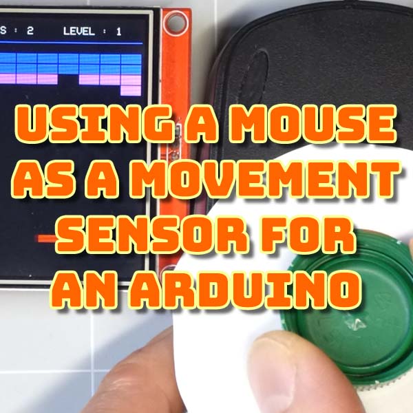
As I said earlier my ultimate goal is to produce a spinner control for an arcade game pad. This will simply consist of a mouse sensor looking at a disc. The disc will be attached to a spinner knob so as you turn the knob the mice will sense the movement of the disc to give you the feedback.
As an example program for the LCD screen I wrote a breakout clone (or Arkanoid). This is a game which is ideal for the spinner control. Modifying the existing code to use the mouse was very straightforward with only the bat movement function having to be updated. With that in place we now have a much more authentic controller for our game, obviously ignoring the fact that it’s a bit of a botched job at the moment – please watch the video!
So please do have a look connecting a mouse to your Arduino. Think of it more as a multi-axis movement detector rather than a screen pointing device and you’ll find much more use for it.


