Wii Gaming on Your PC – Full Wii Remote and Sensor Bar Integration
4th April 2022
Multi Thread Coding on the Raspberry Pi Pico in Micropython
19th April 2022Pi Pico SPI LCD Driver Using RAM Frame Buffer – ILI9341 and ST7789
I’ve already looked at how we can attach a serial SPI LCD screen to our Raspberry Pi Pico and how easy it is to get that up and running with MicroPython. But the basic driver I used was writing individual commands to the screen to draw each object that we wanted to render. Whilst this is great for some applications such as an instrument panel mimic it’s really not very good for any sort of fast moving display such as a mini games console.
So in this tutorial I’ll show you how to use a memory based display buffer to speed up the overall frame rate.
You can find all the code for this project on my GitHub repository at https://github.com/getis/pi-pico-spi-lcd-ili9341-st7789
Getting Started
To start you’ll need to get your Raspberry Pi Pico MicroPython development system up and running and talking to your board. I’ve covered this in detail in my getting started tutorial so please have a look there if you need some help.
You’ll also need your Pi Pico connected to an SPI LCD panel, and again I’ve made a video showing you how to do that. The device I’m using is based on the ILI9341 driver chip. If you’re using an LCD panel based on a different chip set that’s fine. All we need is the ability to drive the display and send it blocks of display data. So as long as your driver provides these functions you’re good to go.
So once you’ve got the basic software and hardware set up we’re ready to build our updated display driver.
Building On Top Of The Existing Driver
The software interface to the LCD panel isn’t going to change in this new driver version. This means that we can use the ILI9341 library from the previous tutorial, or the driver you’ve installed for your display. We’re not going to modify the way the driver library works, just the way we’ll be using it.
If you want to use the same driver as me you’ll find it at this web address.
https://github.com/rdagger/micropython-ili9341
So we first need to set up a clean project for our new tests. I use PyCharm as my development software but feel free to use whatever package suits you.
Don’t forget that once you’ve created the project in PyCharm you need to go to the project settings and enable MicroPython support. This will then load a few extra modules before you’re ready to start.
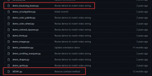
We then need to copy over the main driver file, ILI9341.py, from the library package. I’m also copying over the demo_bouncing_boxes.py file so we have a starting point for our tests. These are the only files we’ll need for now.
Updating the Boxes Demo
At the moment the boxes demo is a bit inflexible when it comes to what we’ll want to do.
We need to be able to easily adjust the number of boxes on screen, and, for reasons we’ll see later, we need to be able to adjust the active display area.
# generate boxes
boxes = [Box(319, 239, randint(7, 40), display,
             color565(randint(30, 256), randint(30, 256), randint(30, 256))) for i in range(75)]
class Box(object):
    """Bouncing box."""

    def __init__(self, screen_width, screen_height, size, display, color):
        """Initialize box.

        Args:
            screen_width (int): Width of screen.
            screen_height (int): Width of height.
            size (int): Square side length.
            display (ILI9341): display object.
            color (int): RGB565 color value.
        """
        self.size = size
        self.w = screen_width
        self.h = screen_height
        self.display = display
        self.color = color
So I’m adding some code to the main loop to generate a controllable number of randomly sized and coloured boxes so we can easily increase and decrease the workload on the system.
I’m also adding in a couple of variables so we can easily adjust the active screen area we want to use. Although for now I’m setting that at the full 320 x 240 pixel size.
Finally the original demo had some frame rate limiting code in place. With very few boxes on screen this stopped them from moving too fast. But we want this code to run as fast as possible to compare our display driver performance. So, I’m removing that code.
Adding a Frame Rate Display
To see if we’ve managed to improve performance we’ll need a way of measuring it. The boxes demo loops through each box to animate its movement. It then repeats this process forever. This gives us an effective frame render every time it finishes the box rendering loop.
We can add a timer to measure how long it takes to render 100 frames and convert that to a frame rate value. Measuring over 100 frames should give us a good average rate value. We can then simply print it out to the console, which will let us see the result on our REPL interface.
So we need to set a frame counter and a start time variables before the main loop. Then after we count 100 frames we’ll log the time taken, convert it to a frame rate, and then reset everything so we can measure the next 100 frames.
start_time = ticks_us()
frame_count = 0

while True:
    timer = ticks_us()
    for b in boxes:
        b.update_pos()
        b.draw()

    frame_count += 1
    if frame_count == 100:
        frame_rate = 100 / ((ticks_us() - start_time) / 1000000)
        print(frame_rate)
        start_time = ticks_us()
        frame_count = 0
All of the code I’m using in this tutorial will be available in a GitHub repository that I’ll link to in the description below and also from the project page for this video on my main BytesNBits.co.uk website.
Initial Frame Rate
If we upload this to the Pi Pico and then use the REPL interface to run the code we’ll see that the boxes are all animated as we expect.
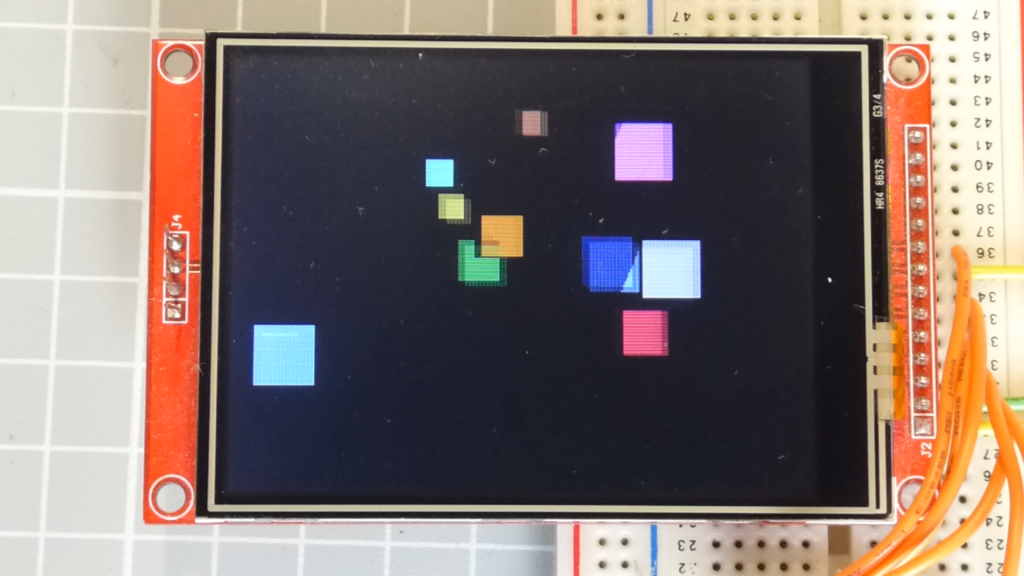
If your code isn’t working please check your typing, or please download the demo software from my GitHub repository.
This demo renders each box by sending a block of pixel data to the LCD panel over the SPI interface. This pixel data is then written into the LCD panel’s display memory and it appears on the screen. To animate the box the code then has to send a second block of pixel data to overwrite the previous one and set the pixels back to the background colour, effectively rubbing it out before sending the next frame.
This means that each box takes two data transfers to complete one frame.
As you can see from the demo with only a few boxes we get a really good frame rate, but as we add more boxes this drops off dramatically.
This shows that this technique is very dependent on how many objects you are animating.
If we increase the box sizes, again you’ll see that the frame rate is very quickly reduced. Each data transfer now takes more time to complete due to the amount of data being sent.
So, if things aren’t updating frequently, or there aren’t many objects, or the objects are small, this overwriting technique will work fine. But increase the workload and you quickly run out of frames.
What is Frame Buffer?
We’re going to use a frame buffer to improve performance.
So what is a frame buffer?
At the moment we’re writing everything directly to the LCD screen memory. This all has to go over the SPI interface which becomes the bottleneck. We simply can’t get the data transmitted fast enough. Plus, if two boxes are overlapping we’re sending pixel data that can’t actually be seen, wasting precious bandwidth.
With the frame buffer we’ll create a copy of the LCD panel memory in the Pi Pico memory and direct all our drawing commands to that. The basic theory is that writing shapes, etc. to internal memory is much, much faster than writing to the LCD screen memory over SPI. We’re doing direct memory access rather than using the slow serial channel. We can therefore render all our objects into the frame buffer. Once we’ve built the next frame we use a single block write command to send the fully rendered screen to the LCD panel in one go.
Performance
Each frame therefore requires a full panel’s worth of pixel data to be sent over the SPI interface. This makes the frame display more predictable as the amount of data being sent over SPI is fixed and independent of what’s being displayed on screen.
Of course, the overwrite method will be faster if the total display data is much less than a full screen’s worth, but the frame buffer will very quickly win out as the display gets more complex.
Also, some of the drawing algorithms send individual pixels to the LCD. Each separate write over SPI has an overhead of command codes and command data bytes. So, although you may be setting one pixel it might use 3 or 4 pixels worth of data. Again this adds to the bandwidth required per frame further slowing down the simpler direct write method.
Building the Frame Buffer
To build a frame buffer requires you to create a memory object in Python. This can be done using a Byte Array. This is simply an array of character values, or single byte integers, that relates to a block of memory inside the Pi Pico.
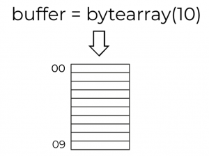
As the LCD panel uses a 16 bit colour value for each pixel we’ll need 2 bytes per pixel.
We then need to be rework our screen drawing functions to write to the frame buffer rather than to the LCD panel directly.
Luckily the MicroPython language has a built-in frame buffer object that will do everything we need.
To use it you simply need to include the built-in library in your code.
import framebuf
We then need to create our memory storage as a Byte Array and then instantiate a frame buffer instance with this memory buffer data.
# FrameBuffer needs 2 bytes for every RGB565 pixel
buffer_width = 240
buffer_height = 140
buffer = bytearray(buffer_width * buffer_height * 2)
fbuf = framebuf.FrameBuffer(buffer, buffer_width, buffer_height, framebuf.RGB565)
Here we are telling it which bytearray to use, what the screen dimensions are and finally that we are using the 565 format to encode the pixel colour data into 16 bits.
If you then have a look at the FrameBuffer documentation.
https://docs.micropython.org/en/latest/library/framebuf.html
You’ll see that it contains several primitive drawing functions, very similar to the ones in the ILI9341 driver library.
So we can now use these drawing functions to render a frame of our display. Once we’ve rendered and displayed a frame we don’t need to rub out the objects one by one, we can simply clear out the bytearray and then rebuild the next frame from scratch.
fbuf.fill(colors[colour])
To render the frame onto the LCD panel we simply need to issue one block write command that targets the full screen area and uses our bytearray as the pixel data.
display.block(int((320 - buffer_width) / 2), int((240 - buffer_height) / 2),
              int((320 - buffer_width) / 2) + buffer_width-1,
              int((240 - buffer_height) / 2) + buffer_height-1, buffer)
Updating the Bouncing Boxes Demo
We’ve now got all the information and tools to rewrite the bouncing boxes demo using our frame buffer.
In this code I’ve simply modified the Box class to use the FrameBuffer as its display rather than the ILI9341 library. When we create a Box object we pass a reference to the fbuf frame buffer object and then the Box render method uses the FrameBuffer fill_rect method to draw it into the frame memory.
Then in our main code we create our bytearray and frame buffer objects and then run the main loop moving and rendering the boxes, clearing the screen after each frame render.
Oooops! It Doesn’t Work!
If we upload all the files and then run the new demo from our REPL console we’ll immediately get an out of memory error.
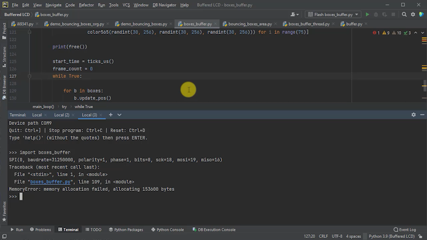
This is the big drawback for using a memory mapped frame buffer in a small microcontroller. Even though the Raspberry Pi Pico is a powerful microcontroller, it still only has 240KB of RAM. If we take our 320 by 240 pixel display that’s 76800 pixels. With 2 bytes per pixel our byte array need to be 153,600 bytes in size or around 150KB.
Although this sounds like there is 90KB left, MicroPython needs some RAM for it’s internal processing along with any other program data we might be using. So very quickly our ‘spare’ RAM is eaten up by the environment.
Reducing RAM Usage
So we need to reduce the amount of RAM our frame buffer uses.
There are two ways to do this.
We can simply use less pixels. By limiting the size of our display we immediately use less memory. A lot of my coding tutorials use TIC80 for writing games and that works great at 240 by 136.
240 x 136 x 2 = 65,280 or 64KB
Indeed you can buy LCD panels at this resolution.
We can also reduce the number of bytes per pixel. This is the method used by most of the 8 bit computers from the 1980’s where they had to fit a memory mapped frame buffer into a 64KB memory address space.
If we used 8 bit colour, giving us 256 possible colours we instantly halve our memory use at 1 byte per pixel.
Going to 4 bit colour resolution, giving 16 colours, we can fit two pixels into each byte.
Or go all the way to 1 bit colour, basically black and white, we get eight pixels per byte.
Limitations of MicroPython
Ideally I would like to run the display at full size using 8 bit colour resolution. I did write a frame buffer to use this but to convert the 8bit pixels values to 16bit colours for the LCD panel requires you to process each individual pixel as you pull it out of the frame buffer memory. Python could do it, but only at around 5 seconds per frame. So not really useable!!
So that’s something I’ll have to come back to with some C++ coding.
For now we’ll have to use the smaller screen area to get a useable Python solution.
Reducing the Active Screen Area
Using a smaller screen area is a fairly easy fix in the code. This was the main reason for holding the screen dimensions as variables rather than hard coding – remember always avoid building ‘magic’ numbers into your code.
In this version I’m setting the screen dimensions to match the TIC80 display and then reworking the block display so that it centres this on the screen.
So now when we run the code the Pi Pico has enough memory and we get our bouncing boxes.
We can now increase the number of boxes and our frame rate becomes much less dependent on the complexity of our animations.
Running 10 boxes gives us around 44 frames per second which is comparable with the standard driver performance.
At 50 boxes our standard driver was only able to get around 3fps. But our frame buffered driver is still giving a very respectable 30fps.
Even if we we run at 100 boxes we still get a frame rate of around 22fps.
Using a Smaller LCD Panel
Our frame buffered solution now gives us a display driver that we can use in a much wider range of applications, providing that we are content with the reduced screen size.
The 320 x 240 pixel LCD panel I’m currently using is now a bit of an overkill with lots of wasted space, so let’s try one of the correctly sized panels for our new driver.
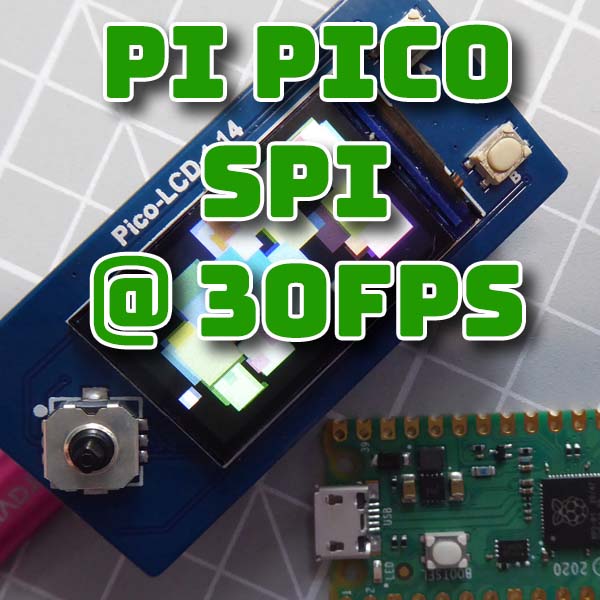
If you look around you’ll come across a number of 240 x 135 pixel panels. The one I have here is a Waveshare panel that has a 1.14 inch display along with a joystick control and two buttons that simply plugs onto the bottom of the Raspberry Pi Pico.
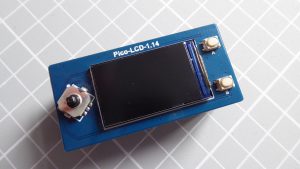
Get this on Amazon – https://amzn.to/376PWC7
This panel uses a different driver chip, the ST7789. If you go to this GitHub repository you’ll find a suitable MicroPython driver library which we can use in our project.
https://github.com/russhughes/st7789py_mpy
I’m integrating this code by simply creating a new file in my project and pasting in the raw code from the driver file.
If we then have a look at the pinout for the LCD panel we can work out what pins are being used to connect the two devices together.
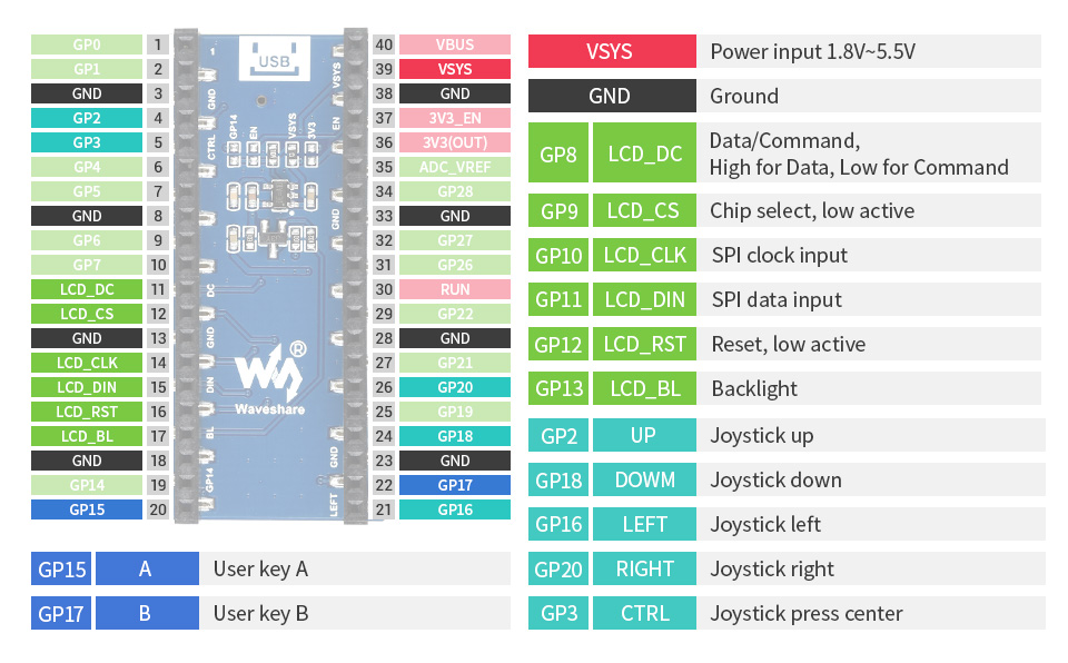
Here we’re mostly using the SPI1 channel pins on GP10 and GP11.
In our box_buffer code we need to import our ST7789 class and update our SPI interface setup to send the data to the correct port. We can then instantiate our ST7789 driver class and supply it with the rest of the pin numbers.
import st7789 as st7789
screen_width = 135
screen_height = 240
screen_rotation = 1

spi = SPI(1,
          baudrate=31250000,
          polarity=1,
          phase=1,
          bits=8,
          firstbit=SPI.MSB,
          sck=Pin(10),
          mosi=Pin(11))

display = st7789.ST7789(
    spi,
    screen_width,
    screen_height,
    reset=Pin(12, Pin.OUT),
    cs=Pin(9, Pin.OUT),
    dc=Pin(8, Pin.OUT),
    backlight=Pin(13, Pin.OUT),
    rotation=screen_rotation)
Our Box class already uses the frame buffer for all its drawing operations so the only other modification we need is to change the block write command that sends the buffer memory out to the screen. Almost all LCD drivers will have a block write command. This ST7789 driver has a blit_buffer method that does exactly the same job. So we simply replace our block method call with a blit_buffer call, and update the screen coordinates to use the full LCD panel size.
display.blit_buffer(buffer, 0, 0, buffer_width, buffer_height)
If we now upload all of this to the Pico and run the new boxes demo we’ll get our bouncing display running full screen.
Conclusion
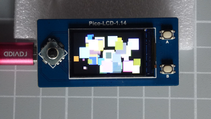
So this gives us a very usable SPI display driver for our Pi Pico. With the smaller LCD board with integrated controller buttons we’ve basically got the bare bones of a small handheld console to develop some MicroPython games with. All we need to do is build out the frame buffer methods to handle sprites and so on and we’re ready to go.
Having said that though there is one other route I’ll be taking for this project in the next video. That’s to use the second core on the Raspberry Pi Pico to run the SPI interface in parallel with the game logic. But multi core processing really does deserve its own video.

