Bare Metal Emulation of the ZX Spectrum With ZXBaremulator
24th November 2023
Temu and AliExpress – Good or Bad?
17th December 2023Make Your Own Replica ZX Spectrum – ZXBaremulator + Original Case and Keyboard
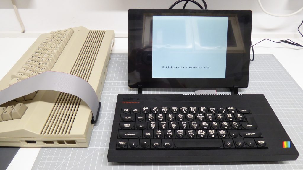
In one of my last videos we set up a bare metal emulator for the ZX Spectrum using ZXBaremulator. This gave us a Raspberry Pi that booted up in just a few seconds taking us straight to a fully emulated ZX Spectrum. At the time I mentioned that this setup is ideally suited to building a replica machine using the keyboard and case from an original Speccy.
So, let’s do just that in this video.
ZX Baremulator
To start with you’ll need to get your Raspberry Pi set up with the emulator, so please work your way through the installation video.
Original Hardware
To build the project you’ll also need an original ZX Spectrum case and keyboard. We don’t need a working motherboard or any other power supplies or add-ons, so have a look on eBay to pick up a non working computer. The original 16/48K model, Spectrum + and the 128K machines will all work great for this project. The +2 and +3 use a different keyboard matrix so the ZXBaremulator won’t be able to correctly scan those models.
When you are buying your computer try to make sure that the keyboard is in good condition otherwise you’ll need to replace some of the parts which can push the cost up. If you do need some parts there are a number of suppliers you can use
Some of these parts suppliers also sell refurbished cases and keyboards, or even brand new parts that you can build a new system from.
So have a look around to see what route suits you best.
Which Raspberry Pi to Use?
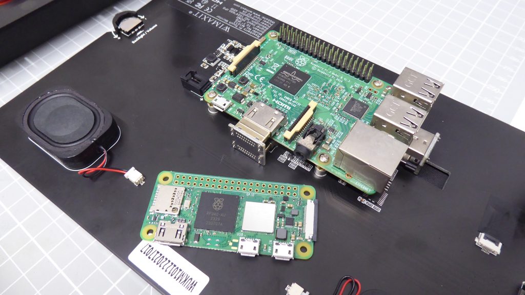
In the installation video I used a Raspberry PI Zero 2W. In my opinion this is the best option for embedding a Raspberry Pi in the actual case. But I’m going to propose two options on how you mount your board.
The circuit we’ll build will basically mount the Raspberry Pi so that it pokes out through the main expansion slot in the back of the Spectrum case. This is why I prefer to use the Pi Zero as all of its ports, HDMI, power and USB are mounted along one edge of the board and nicely spaced so that they will fit into the available slot.
But this does mean that you need to dedicate your Raspberry Pi to the project.
The second option is to mount a 40 way IDC connector in the expansion slot and run a ribbon cable to the GPIO connector on a Raspberry Pi mounted elsewhere. We can organise the circuit so that all the connections to the original hardware are made through this GPIO cable. In my setup I have a Raspberry Pi 3B+ mounted in the back of an Elecrow 11 inch monitor which keeps all the power and video cables very neatly out of the way.
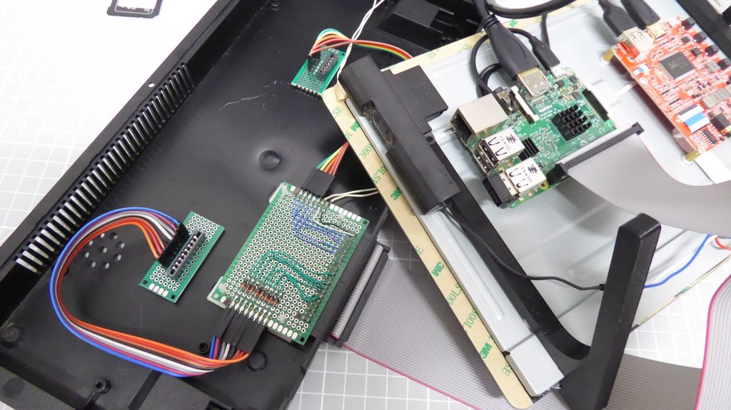
I’ve actually used this mounting method on my replica Commodore 64 (link below) so that I now have a growing number of retro computer keyboard and case units that I can swap in and out of my setup, just needing to also swap over the SD card to run the different emulators. For me this works better than having dedicated RPis in each case and swapping over all the cables.
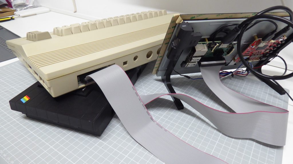
Either way it’s your choice and we’ll see both methods today.
The Interface Circuit
The ZX Spectrum emulator just requires us to connect to the keyboard membrane ribbon cables. There are two of these at each end of the keyboard to carry the row and column lines for the keyboard switch matrix. These ribbon cables need special push fit connectors to mount them onto a circuit board, but they are easy to find online. You can solder flying leads directly onto the ribbon cables but I’d advise against this. I can’t give you a valid technical reason for this. It just doesn’t seem right to me!
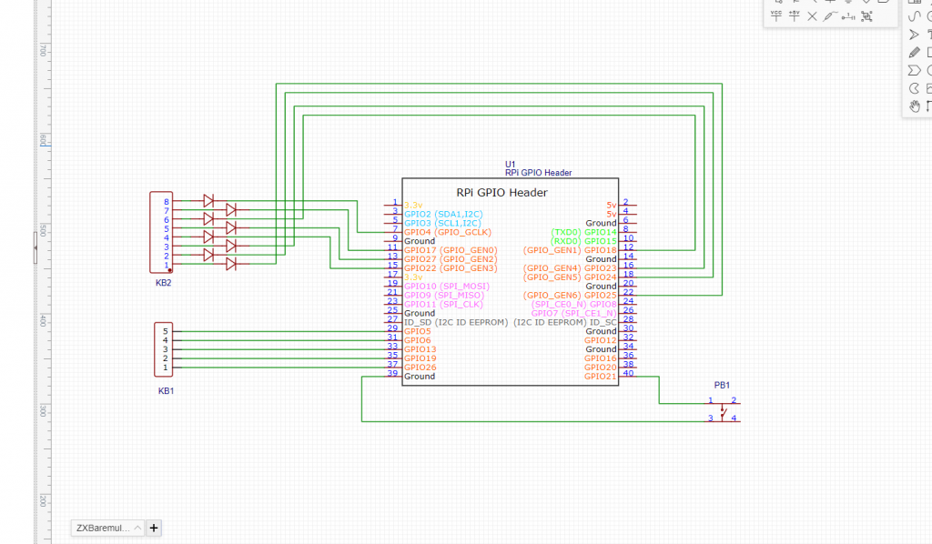
These lines are then just fed onto some GPIO pins so that the Raspberry Pi can drive the matrix. We do need to fit some small signal diodes onto the eight way connector lines to avoid multiple, simultaneous key presses causing short circuits on the matrix.
The Extra Button
To navigate inside the ZXBaremulator settings we need access to some function keys that don’t exist on the ZX Spectrum. To get around this the emulator uses an alternate keyboard mode that’s activated by a separate button. This momentary push button just pulls one of the GPIO lines low which is then monitored by the software.
On my ZX Spectrum + case there is a small reset button on the left hand side which can be used. If your case doesn’t have one, you’ll need to use a button mounted in one of the cutouts at the back of the machine.
Full Circuit
This gives us a final circuit for the project.
Testing the Circuit
To make sure that everything is working correctly it’s best to build the circuit on some breadboard. As you can see on screen at the moment I’ve created two small circuit boards to mount the ribbon cable connectors and allow them to be easily connected to my breadboard using some flying leads and pin headers. The breadboard also contains the 8 signal diodes to protect the circuit and I then used a GPIO breakout board to connect the keyboard signals to my Raspberry Pi.
For now, I’m just using a separate push button to activate the alternate keyboard.
Once everything is built up, powering on the circuit should give you a fully working ZX Spectrum keyboard.
What If It Doesn’t Work?
If you find your circuit isn’t working there are number of possible causes.
Firstly, make sure you check your wiring both for wrong connections and also make sure the ribbon cables are securely seated in their connectors.
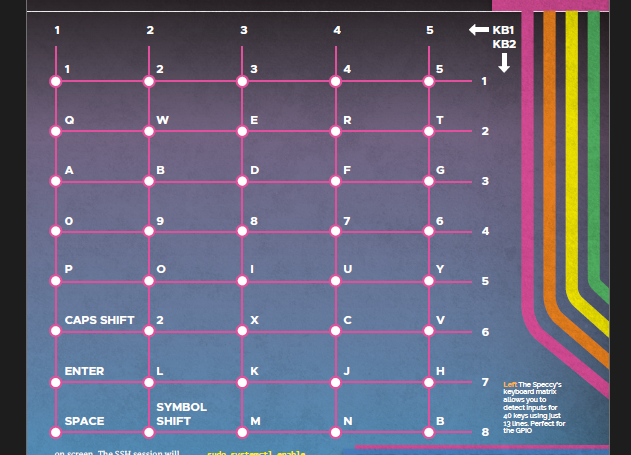
If you still find you’ve got some keys not working it might be that your keyboard membrane has a fault. One of the common faults is that the traces on the ribbon cables fracture, breaking the signal line. The keyboard matrix is laid out as shown in this diagram. If one of your membrane signals is not working you’ll find either a row or a column of keys aren’t responding. If this is the case you’ll need to replace the membrane. Please have a look at this video on how to do that.
If you find that individual keys aren’t working, rather than a block of keys, then you’ll have an issue with either the key mechanism itself or the keypad on the membrane. If you take the membrane out of the keyboard and connect it up you should be able to press all the keys to test if the keypads are working correctly. If all the key pads are working correctly then you’ll need to check the key mechanism to make sure but when you press the key it actually makes contact with the membrane pad.
Eventually, you should be able to solve all your issues and arrive at a working machine.
Building the Circuit
Eventually I’ll take you through the process of designing and building your own PCB, but for now I’m going to use a quick and easy method of prototyping a circuit. There are a number of options for this but my preferred technology is matrix board with wire wrapping wire connections soldered on the back.
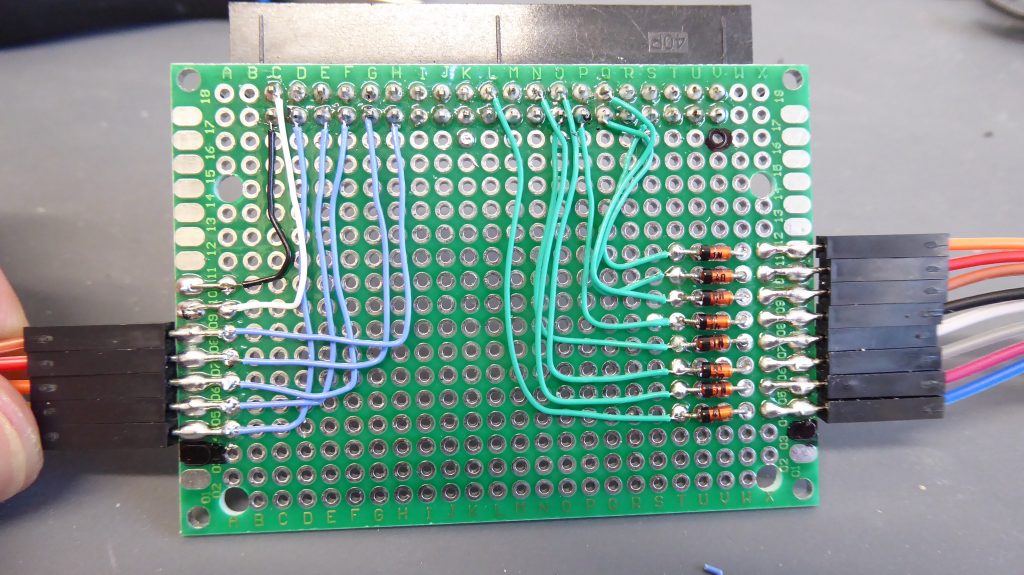
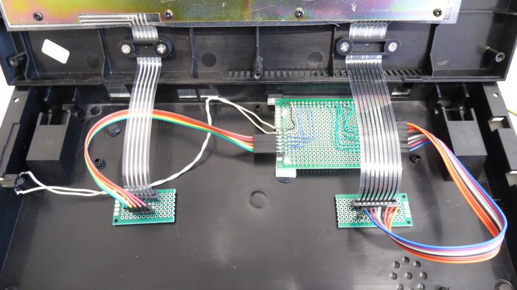
You’ll need at least two circuit boards, one for each of the ribbon cables. These boards simply need the matching ribbon cable connector with some flying leads to connect the signals lines to the main board. If you look at a real Spectrum motherboard you’ll see the general location for the connectors. These positions allow the ribbon cables to naturally bend so that they don’t get damaged.
To mount mine I simply attached the boards to the end of the ribbon cables and placed the case top in place. I then hot glued the boards into place where they naturally fell, allowing some slack so the case could easily be opened.
The last circuit board we need is either a Raspberry Pi Zero, or a main board with a 40 way IDC male connector.
If you use a Raspberry Pi you’ll need to mount it in the rear expansion slot so that you have access to the IO ports. Your best bet is to use very short PCB standoffs or simply hot glue the Pi in place as the expansion port cutout isn’t very tall. You can then plug your flying leads directly onto the Pi and you’re all set to go.
I’m going to use a ribbon cable connection to an external Raspberry Pi so I needed to build a small circuit board to interface between the flying leads and the IDC connector. To mount it into the expansion slot I actually mounted the IDC connector on the bottom of the board and then used PCB standoffs to mount the assembly in the expansion slot. I used a unpopulated matrix board in the bottom of the expansion slot to create a spacer as I mounted the board so that the connector wasn’t flat against the case. My standoffs were about 1-2 mm too short so I just used a bigger blob of hot glue to lift them off the base a bit more. In the end this gave a very neat rear port connection.
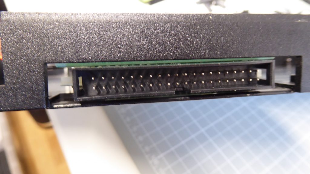
All that was needed then was to connect a 40 way ribbon cable from the Spectrum to my Raspeberry Pi mounted in the back of my mini LCD monitor.
Testing the Circuit
At this point we should have a fully working replica ZX Spectrum.
To test that all the keys are working power up the emulator and type in this line of code without pressing enter at the end.
10 REM
The REM command is on the E key.
This should now let you test all the keyboard keys to make sure they both work and report back the correct key press.
When I tested mine I found that a few of the keys were swapped round. My 4 and 5 keys were swapped, along with the R and T, the F and G, H and J etc.
Again looking at the keyboard matrix you can see that my KB1 lines 4 and 5 were swapped. And indeed on looking at the flying leads on the connector board I could see the twist in the last two wires. Swapping these over fixed the issue.
What Next?
So that’s a completely working replica ZX Spectrum. The circuits we’ve built are fine to give you a working system but may not be the most elegant solution.
To make the whole installation a bit better we can make a custom PCB to hold everything together a bit more securely. But we’ll have to leave that for another video.
