Fix Sound Problems on Raspberry Pi Zero With GPIONext – Building Your Own Retro Gaming Handheld
24th May 2021
Raspberry Pi I2S Sound – Add Digital Sound Output to Your Raspberry Pi
30th May 2021Raspberry Pi Zero Sound Output – Add Analog Sound Through a Headphone Socket and Speaker
(This page is part of the Raspberry Pi Handheld Games Console series. Please click here for the full project.)
Adding Sound To Your Raspberry Pi Zero
One of the differences between a full-sized Raspberry Pi and a Raspberry Pi Zero is the audio output jack. The full-sized Raspberry Pi is a dedicated sound output circuit connected to this stereo jack plug so that you can easily get sound out of the device without having to rely on an HDMI connection. The Raspberry Pi Zero still contains the sound generation functionality but lacks any on-board circuitry to give you access to that sound.
If we’re going to use a Raspberry Pi Zero for our handheld retro games machine we are going to have to build our own sound output circuit and connect it to the device.
Raspberry Pi Zero Sound Output Pins
The first problem we have to overcome is that the sound output pins from the processor aren’t available anywhere on the circuit board. We can however reprogram some of the GPIO pins and rewrite the sound outputs to those. Most of the GPIO pins can perform a number of different functions accessed by putting them into their alternative function modes. The diagram below shows a full list of these alternative settings.
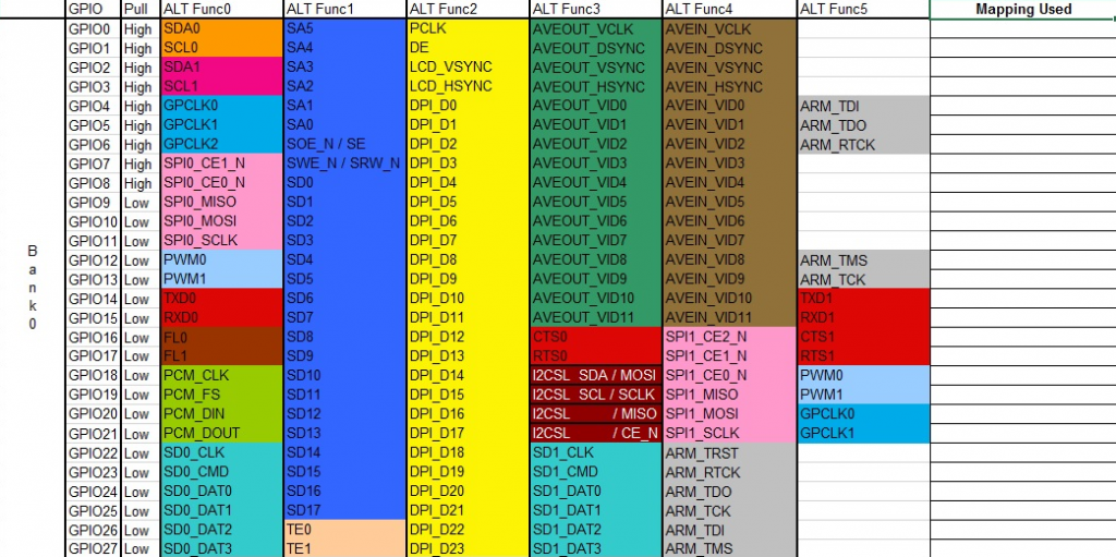
PWM0 and PWM1 carry the left and right stereo sound signals so we can pick these up on either GPIO12 and GPIO13 or GPIO18 and GPIO19.
Setting GPIO Pins to Their Alternative Functions
By default most GPIO pins are set as inputs on bootup. For our sound to work we need to switch them into their alternative modes in our start-up procedure. The easiest way to do this is an our /boot/config.txt file.
To do this we simply need to add a gpio command line as below.
gpio=18,19=a5
This line sets GPIO18 and GPIO19 into their alternative 5 mode which, looking at the diagram above, puts them into PWM mode. We could also use GPIO12 and GPIO13 but for these we need to be in ALT0 mode.
gpio=12,13=a0
If you want more information on how to set GPIO pins are bootup have a look the documentation on the main Raspberry Pi website.
https://www.raspberrypi.org/documentation/configuration/config-txt/gpio.md
Enabling Sound Output
To get the Raspberry Pi to send sound to these pins we need to enable the correct hardware and driver software in the same config.txt file.
Look for the line,
dtparam=audio=on
and make sure that it is not commented out. When the Raspberry Pi boots up this will make sure that the audio output circuitry is enabled.
Checking the GPIO Pins
To make sure that the GPIO pins have been correctly set during start-up we can use a package called WiringPi. You can install this package from the terminal using the following command.
sudo apt-get install wiringpi
Once you got that installed we can use the
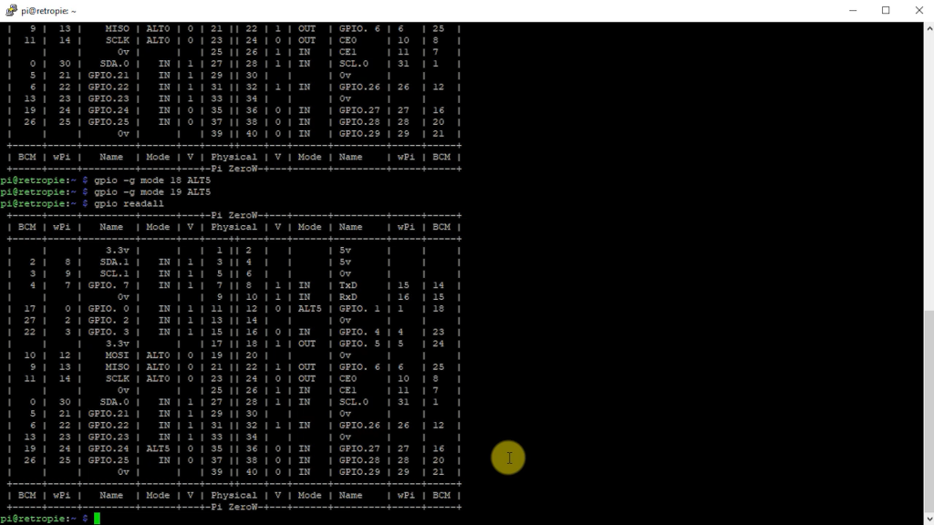
gpio readall
command to get a listing of all the GPIO pins and the current state. If you look in the BCM columns for pins 12 and 13 or 18 and 19 you should see their function listed as ALT0 or ALT5 depending on which sets of pins you’re using.
Making Sure Your Sound Driver Software Is Installed
For the Raspberry Pi to be able to output sound we need to make sure that the alsa-utils package has been installed.
sudo apt-get install alsa-utils
Selecting the Headphones Sound Output
In our handheld games console set up we’ve been forcing the HDMI output to be turned on. This also forces the sound to be routed through the HDMI signal. We need to change this so that the sound is sent to our new headphone output. This is set using the raspi-config utility.
sudo raspi-config
Once the application starts you need to select the system settings, and then the audio settings. You will be given an option to select HDMI sound or the headphone socket. Select the headphones option and then exit from the configuration utility.
After all of this you’ll need to reboot the Raspberry Pi so that all of the settings take effect.
Raspberry Pi Sound Output Circuitry
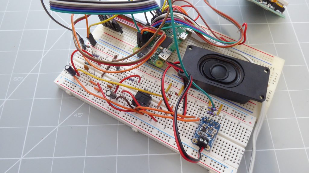
Now that we have the sound signals available on to GPIO pins we need to process this through some circuitry so that we can turn it into audible sound. The circuit we’re going to use is shown below.
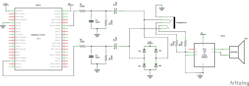
The signals from each of the GPIO pins is first fed into a low-pass filter. The first resistor and capacitor form an RC network which allows lower frequencies to pass through but grounds higher frequencies so they don’t appear on our sound output. The cut off frequency (highest frequency online through the RC network) is given by the equation,
f = 1 / 2pi R C
For the component values I’ve chosen this gives a cut-off frequency of just under 20 kHz which is ideal to let audible sound through but stop most of the unwonted hissing and background noise generated by the electronics.
The second resistor in parallel with the capacitor is really used to attenuate the sound level for the headphone socket.
After that the signal is passed through a decoupling capacitor before being fed onto the headphone socket.
For this setup I wanted to be able to use a headphone cable when wanting to play in private, but also have a loudspeaker available if I needed it. The 3.5 mm headphone jack socket I’ve used has both an input connection and a passthrough connection. When a headphone is plugged into the socket it is connected directly to the sound signal, but also disconnects the passthrough connection on the output side of the headphone socket. This way only the headphones received the sound signal.
When you unplug the headphones the passthrough connections are connected to the sound signal so we can simply connect these to an amplifier which will raise the sound levels so that we can drive a loudspeaker.
The amplifier I’m using is a simple mono amplifier from Adafruit. To feed the stereo signal into this amplifier we need to use two input resistors which will mix the two signals into a single sound channel. This particular amplifier incorporates all the components required to prepare the signals, amplify them, and then provide a simple two wire speaker connection. It also has a built in potentiometer so that we can adjust the volume.
Testing the Audio Circuit
Once the circuit is built and connected and we’ve got the Raspberry Pi configured we should be able to get some sound. The Alsa package we installed earlier has some speaker test functions that we can run.
speaker-test -c2 --test=wav -w /usr/share/sounds/alsa/Front_Center.wav
If everything is working correctly you should hear a voice repeatedly saying, “Front, centre”.
If this doesn’t work I’ve included some fault finding tips in the main video.
Getting RetroPie to Use the Headphone Output
Once you’ve got the sound working from the command line we need to make sure that RetroPie is sending it’s sound to the headphone output as well.
If you go to the settings in RetroPie you’ll find a section for sound. In there you need to set the audio card to default, the audio device to headphones and the very bottom setting to both.
Once you got those settings in place you should have a working game system.
The Next Step
If you’ve managed to get all this working you should have a reasonably good sound output coming from your Raspberry Pi Zero. It does have a bit of background noise in the signal but this shouldn’t be too distracting, especially once your game is making enough noise to cover it over.
Having said that it would be good to try and get a much cleaner sound signal. For this will need to move to the Raspberry Pi Zero digital sound output.
I’ll cover this in the next episode.

