Basic Animation on Your SPI TFT Touchscreen and Arduino
30th November 2020
Coding Games on an ILI9341 SPI LCD Touchscreen with Arduino
3rd January 2021Calibrating and Coding Your Arduino Touchscreen
How a Resistive Touchscreen Works
There are 2 main types of touchscreen technology. Capacitive touchscreens are probably the most common and are found on almost all phones, tablets and laptops. But resistive touchscreens are usually the ones you’ll find on smaller LCD panels for your electronics projects. They are cheaper to make so keep the cost down for your devices.
In simple terms a resistive touch panel is two sheets of film separated by a non conducting layer, usually a gas or liquid. When you press on the screen you force the two film layers to touch and make an electrical connection. The screen’s electronics are able to sense the position of this touch connection using sensors that measure resistance between opposite edges of the panel. Basically the touch point creates a potential divider circuit in both the horizontal and vertical planes of the panel.
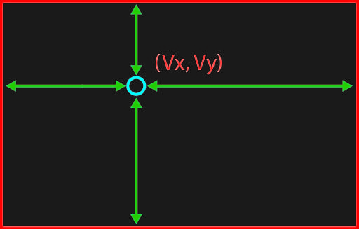
These measurements are then translated into values by a touchscreen driver chip and then made available to the Arduino (or whatever microcontroller you’re using).
Calibrating the Touchscreen and LCD Panel
The touch panel and LCD screen are two separate devices. Although they are bonded together there is no connection between the two. The value sent when you touch the resistive panel don’t match with the pixel coordinate values on the LCD panel. We need to develop an algorithm that will let us translate touch panel coordinates so they match LCD pixel coordinates. This is a process of calibrating the touchscreen.
As we’ve already seen the touch panel driver chip will return X and Y coordinate values based on the resistance measurements horizontally and vertically on the device. These values will vary proportionally across the width and height of the screen. The zero values for the touch panel won’t match the zero values for pixels on the LCD screen, but there will be a linear relationship between the two coordinate systems.
This means that we can model the relationship between the X coordinates on the touch and LCD panels as a straight line graph. Similarly the Y coordinates can be modelled as a separate straight line graph.
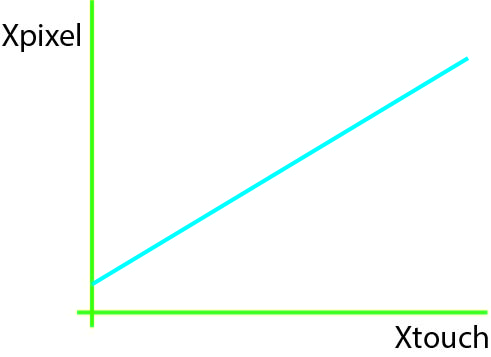
To find the equation of each line we need to take a number of readings so that we can match pixel coordinates with their corresponding touch panel coordinates. The number of readings you need to take depends on how accurately you want to model the connection between the LCD and touch panels. We already looked at the simple horizontal relationships. But this also another manufacturing error that we might want to consider.
When the two panels are joined together the vertical and horizontal grid lines might not be aligned, as shown in the diagram below.
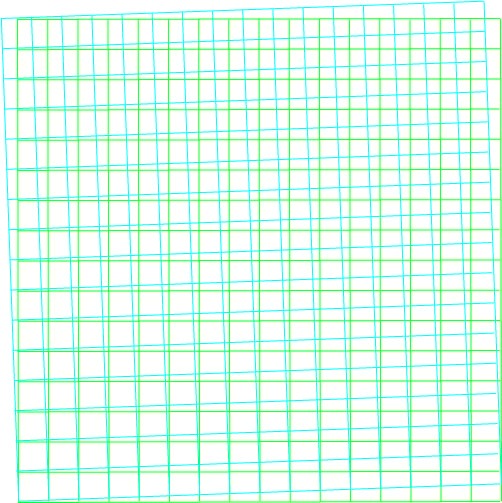
This misalignment can give us an error which will vary across the width and height of the screen.
Having said that, and especially for small screens, this misalignment error is going to be very small. The calibration process involves the user touching the screen at specified points, and the user error is probably going to be bigger than any misalignment error.
For true touch panel calibration, including the misalignment error, you need to use three point calibration. The mathematics for this are a little bit complicated but again you will be able to find an Arduino package which will have this code pre-written for you.
For this project will be using a simple two point calibration which will let us create the linear relationships between the X and Y coordinates but ignore any misalignment errors.
Calculating the Linear Relationships
To calculate the linear equations we need the user to identify two points on the screen. We’ll do this by setting a target in one corner, asking them to touch the target and then reading the touch panel values which can be logged against the known pixel coordinate values of the target. We can then repeat the process in the opposite corner. This gives us two sets of values where we have two sets of X coordinates with pixel values and their matching touch panel values, and two sets of Y coordinate values.
We can then use these to calculate the linear equations for both the X and Y coordinates.
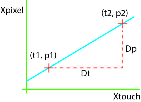
For the X coordinates as shown in the graph above we are trying to create straight-line equation of the form,
Xp = m Xt + c
where m is the gradient of the line and m is the y-axis crossing point.
To calculate the gradient, m, we need to divide the X coordinate pixel distance between the two calibration points by the X coordinate touch panel distance.
m = (p2 – p1) / (t2 – t1)
We can then substitute this value into our equation and use one of our measured points to find the value for c.
Xp = m Xt + c
c = Xp – m Xt
c = p2 – m t2
Once we got the values for our X coordinate linear equation we can simply repeat the process for the Y coordinates.
Coding the Conversion Function
We only need to run the calibration code when the Arduino is first turned on. We can then store linear equations within our software and use them in a conversion function which will allow us to passing or touchscreen coordinates and get back a matching set of screen pixel coordinates.
We wanted to we could also store linear equation parameters in the EEPROM of the Arduino. When we then turn on the Arduino we can check the EEPROM to see if there are any valid parameters and then load those instead of running the full calibration routine.
Building a Touchscreen User Interface
Now that we are able to create graphics on the LCD panel, listen for touch events on the touch panel and convert touch coordinates the screen pixel coordinates, we can start to create buttons, sliders and other user interface components for our projects. This opens up a very powerful and user-friendly way of communicating with you Arduino powered devices. The LCD screen gives you an infinite array of options on how your device communicates back to the user and the touch panel can replace a vast array of buttons and dials. It’s really down to your imagination to work out what you can do with it.
Code Used in the Video
#include "SPI.h"
#include "Adafruit_GFX.h"
#include "Adafruit_ILI9341.h"
#include "XPT2046_Touchscreen.h"
#include "Math.h"

// For the Adafruit shield, these are the default.
#define TFT_CS 10
#define TFT_DC 9
#define TFT_MOSI 11
#define TFT_CLK 13
#define TFT_RST 8
#define TFT_MISO 12

#define TS_CS 7

#define ROTATION 3


// Use hardware SPI (on Uno, #13, #12, #11) and the above for CS/DC/RST
Adafruit_ILI9341 tft = Adafruit_ILI9341(TFT_CS, TFT_DC, TFT_RST);
XPT2046_Touchscreen ts(TS_CS);

// calibration values
float xCalM = 0.0, yCalM = 0.0; // gradients
float xCalC = 0.0, yCalC = 0.0; // y axis crossing points

int8_t blockWidth = 20; // block size
int8_t blockHeight = 20;
int16_t blockX = 0, blockY = 0; // block position (pixels)

class ScreenPoint {
public:
int16_t x;
int16_t y;

// default constructor
ScreenPoint(){
}

ScreenPoint(int16_t xIn, int16_t yIn){
x = xIn;
y = yIn;
}
};

ScreenPoint getScreenCoords(int16_t x, int16_t y){
int16_t xCoord = round((x * xCalM) + xCalC);
int16_t yCoord = round((y * yCalM) + yCalC);
if(xCoord < 0) xCoord = 0;
if(xCoord >= tft.width()) xCoord = tft.width() - 1;
if(yCoord < 0) yCoord = 0;
if(yCoord >= tft.height()) yCoord = tft.height() - 1;
return(ScreenPoint(xCoord, yCoord));
}

void calibrateTouchScreen(){
TS_Point p;
int16_t x1,y1,x2,y2;

tft.fillScreen(ILI9341_BLACK);
// wait for no touch
while(ts.touched());
tft.drawFastHLine(10,20,20,ILI9341_RED);
tft.drawFastVLine(20,10,20,ILI9341_RED);
while(!ts.touched());
delay(50);
p = ts.getPoint();
x1 = p.x;
y1 = p.y;
tft.drawFastHLine(10,20,20,ILI9341_BLACK);
tft.drawFastVLine(20,10,20,ILI9341_BLACK);
delay(500);
while(ts.touched());
tft.drawFastHLine(tft.width() - 30,tft.height() - 20,20,ILI9341_RED);
tft.drawFastVLine(tft.width() - 20,tft.height() - 30,20,ILI9341_RED);
while(!ts.touched());
delay(50);
p = ts.getPoint();
x2 = p.x;
y2 = p.y;
tft.drawFastHLine(tft.width() - 30,tft.height() - 20,20,ILI9341_BLACK);
tft.drawFastVLine(tft.width() - 20,tft.height() - 30,20,ILI9341_BLACK);

int16_t xDist = tft.width() - 40;
int16_t yDist = tft.height() - 40;

// translate in form pos = m x val + c
// x
xCalM = (float)xDist / (float)(x2 - x1);
xCalC = 20.0 - ((float)x1 * xCalM);
// y
yCalM = (float)yDist / (float)(y2 - y1);
yCalC = 20.0 - ((float)y1 * yCalM);

Serial.print("x1 = ");Serial.print(x1);
Serial.print(", y1 = ");Serial.print(y1);
Serial.print("x2 = ");Serial.print(x2);
Serial.print(", y2 = ");Serial.println(y2);
Serial.print("xCalM = ");Serial.print(xCalM);
Serial.print(", xCalC = ");Serial.print(xCalC);
Serial.print("yCalM = ");Serial.print(yCalM);
Serial.print(", yCalC = ");Serial.println(yCalC);

}


void setup() {
Serial.begin(9600);

// avoid chip select contention
pinMode(TS_CS, OUTPUT);
digitalWrite(TS_CS, HIGH);
pinMode(TFT_CS, OUTPUT);
digitalWrite(TFT_CS, HIGH);

tft.begin();
tft.setRotation(ROTATION);
tft.fillScreen(ILI9341_BLACK);
ts.begin();
ts.setRotation(ROTATION);
calibrateTouchScreen();

}

void moveBlock(){
int16_t newBlockX, newBlockY;
ScreenPoint sp = ScreenPoint();
if (ts.touched()) {
TS_Point p = ts.getPoint();
sp = getScreenCoords(p.x, p.y);
newBlockX = sp.x - (blockWidth / 2);
newBlockY = sp.y - (blockHeight / 2);
if (newBlockX < 0) newBlockX = 0;
if (newBlockX >= (tft.width() - blockWidth)) newBlockX = tft.width() - 1 - blockWidth;
if (newBlockY < 0) newBlockY = 0;
if (newBlockY >= (tft.height() - blockHeight)) newBlockY = tft.height() - 1 - blockHeight;
}
if ((abs(newBlockX - blockX) > 2) || (abs(newBlockY - blockY) > 2)){
tft.fillRect(blockX, blockY, blockWidth, blockHeight,ILI9341_BLACK);
blockX = newBlockX;
blockY = newBlockY;
tft.fillRect(blockX, blockY, blockWidth, blockHeight,ILI9341_RED);
}
}

unsigned long lastFrame = millis();

void loop(void) {

// limit frame rate
while((millis() - lastFrame) < 20);
lastFrame = millis();

if (ts.touched()) {
moveBlock();
}

}
#include "SPI.h"
#include "Adafruit_GFX.h"
#include "Adafruit_ILI9341.h"
#include "XPT2046_Touchscreen.h"
#include "Math.h"

// For the Adafruit shield, these are the default.
#define TFT_CS 10
#define TFT_DC 9
#define TFT_MOSI 11
#define TFT_CLK 13
#define TFT_RST 8
#define TFT_MISO 12

#define TS_CS 7

#define ROTATION 3


// Use hardware SPI (on Uno, #13, #12, #11) and the above for CS/DC/RST
Adafruit_ILI9341 tft = Adafruit_ILI9341(TFT_CS, TFT_DC, TFT_RST);
XPT2046_Touchscreen ts(TS_CS);

// calibration values
float xCalM = 0.0, yCalM = 0.0; // gradients
float xCalC = 0.0, yCalC = 0.0; // y axis crossing points

int8_t blockWidth = 20; // block size
int8_t blockHeight = 20;
int16_t blockX = 0, blockY = 0; // block position (pixels)

class ScreenPoint {
public:
int16_t x;
int16_t y;

ScreenPoint(){
// default contructor
}

ScreenPoint(int16_t xIn, int16_t yIn){
x = xIn;
y = yIn;
}
};

class Button {
public:

int x;
int y;
int width;
int height;
char *text;

Button(){
}

void initButton(int xPos, int yPos, int butWidth, int butHeight, char *butText){
x = xPos;
y = yPos;
width = butWidth;
height = butHeight;
text = butText;
render();
}

void render(){
tft.fillRect(x,y,width,height,ILI9341_GREEN); // draw rectangle
tft.setCursor(x+5,y+5);
tft.setTextSize(2);
tft.setTextColor(ILI9341_WHITE);
tft.print(text);
}

bool isClicked(ScreenPoint sp){
if ((sp.x >= x) && (sp.x <= (x+width)) && (sp.y >= y) && (sp.y <= (y+height))){
return true;
}
else {
return false;
}
}
};

ScreenPoint getScreenCoords(int16_t x, int16_t y){
int16_t xCoord = round((x * xCalM) + xCalC);
int16_t yCoord = round((y * yCalM) + yCalC);
if(xCoord < 0) xCoord = 0;
if(xCoord >= tft.width()) xCoord = tft.width() - 1;
if(yCoord < 0) yCoord = 0;
if(yCoord >= tft.height()) yCoord = tft.height() - 1;
return(ScreenPoint(xCoord, yCoord));
}

void calibrateTouchScreen(){
TS_Point p;
int16_t x1,y1,x2,y2;

tft.fillScreen(ILI9341_BLACK);
// wait for no touch
while(ts.touched());
tft.drawFastHLine(10,20,20,ILI9341_RED);
tft.drawFastVLine(20,10,20,ILI9341_RED);
while(!ts.touched());
delay(50);
p = ts.getPoint();
x1 = p.x;
y1 = p.y;
tft.drawFastHLine(10,20,20,ILI9341_BLACK);
tft.drawFastVLine(20,10,20,ILI9341_BLACK);
delay(500);
while(ts.touched());
tft.drawFastHLine(tft.width() - 30,tft.height() - 20,20,ILI9341_RED);
tft.drawFastVLine(tft.width() - 20,tft.height() - 30,20,ILI9341_RED);
while(!ts.touched());
delay(50);
p = ts.getPoint();
x2 = p.x;
y2 = p.y;
tft.drawFastHLine(tft.width() - 30,tft.height() - 20,20,ILI9341_BLACK);
tft.drawFastVLine(tft.width() - 20,tft.height() - 30,20,ILI9341_BLACK);

int16_t xDist = tft.width() - 40;
int16_t yDist = tft.height() - 40;

// translate in form pos = m x val + c
// x
xCalM = (float)xDist / (float)(x2 - x1);
xCalC = 20.0 - ((float)x1 * xCalM);
// y
yCalM = (float)yDist / (float)(y2 - y1);
yCalC = 20.0 - ((float)y1 * yCalM);

Serial.print("x1 = ");Serial.print(x1);
Serial.print(", y1 = ");Serial.print(y1);
Serial.print("x2 = ");Serial.print(x2);
Serial.print(", y2 = ");Serial.println(y2);
Serial.print("xCalM = ");Serial.print(xCalM);
Serial.print(", xCalC = ");Serial.print(xCalC);
Serial.print("yCalM = ");Serial.print(yCalM);
Serial.print(", yCalC = ");Serial.println(yCalC);

}


Button button;

void setup() {
Serial.begin(9600);

// avoid chip select contention
pinMode(TS_CS, OUTPUT);
digitalWrite(TS_CS, HIGH);
pinMode(TFT_CS, OUTPUT);
digitalWrite(TFT_CS, HIGH);

tft.begin();
tft.setRotation(ROTATION);
tft.fillScreen(ILI9341_BLACK);
ts.begin();
ts.setRotation(ROTATION);
calibrateTouchScreen();
button.initButton(50,50,125,30,"Click Me");

}


unsigned long lastFrame = millis();

void loop(void) {

ScreenPoint sp;

// limit frame rate
while((millis() - lastFrame) < 20);
lastFrame = millis();

if (ts.touched()) {
TS_Point p = ts.getPoint();
sp = getScreenCoords(p.x, p.y);
if(button.isClicked(sp)){
tft.setCursor(50,100);
tft.setTextSize(2);
tft.setTextColor(ILI9341_WHITE);
tft.print("Clicked");
}
else {
tft.fillRect(50,100,125,30,ILI9341_BLACK); // draw rectangle
}
}
else {
tft.fillRect(50,100,125,30,ILI9341_BLACK); // draw rectangle
}

}
Links
LCD module – Amazon
https://amzn.to/35quUJF
LCD eBay
https://rover.ebay.com/rover/1/710-53481-19255-0/1
ILI9341 Library
https://github.com/adafruit/Adafruit_ILI9341
XPT2046 Library
https://github.com/PaulStoffregen/XPT2046_Touchscreen
Adafruit GFX Library
https://github.com/adafruit/Adafruit-GFX-Library
Adafruit LCD tutorial
https://learn.adafruit.com/adafruit-2-8-and-3-2-color-tft-touchscreen-breakout-v2/spi-wiring-and-test
Adafruit GFX Library Tutorial
https://learn.adaruit.com/adafruit-gfx-graphics-library/overview


