Play Every Retro Console and Arcade Game with RetroBat – full installation and setup
25th January 2024
Easiest and Fastest Way to Hack Your Wii – Softmodding With ModMii
7th February 2024ESP32 + 7in LCD + Fast RGB Interface – 30 fps frame rate
Today we’re going to take a look at the new 7 inch LCD touch panel from Elecrow. This unit has a built in ESP32 S3 microcontroller using a 16bit RGB interface to control the screen. This gives us a full 800 x 480 pixel resolution with 64K colours but still allows us to achieve a very respectable 20 to 30 fps, full screen refresh rate. At around £30 for a large screen with powerful microcontroller this is a great value display solution. So, let’s take a closer look.
The 7in LCD Touch Panel
The unit comes as a single item with the ESP32 circuit board mounted on the back of the LCD panel.
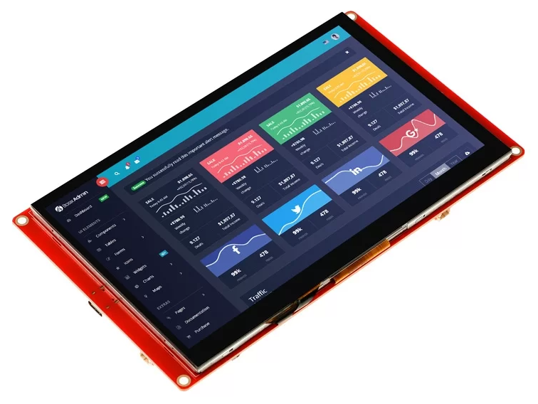
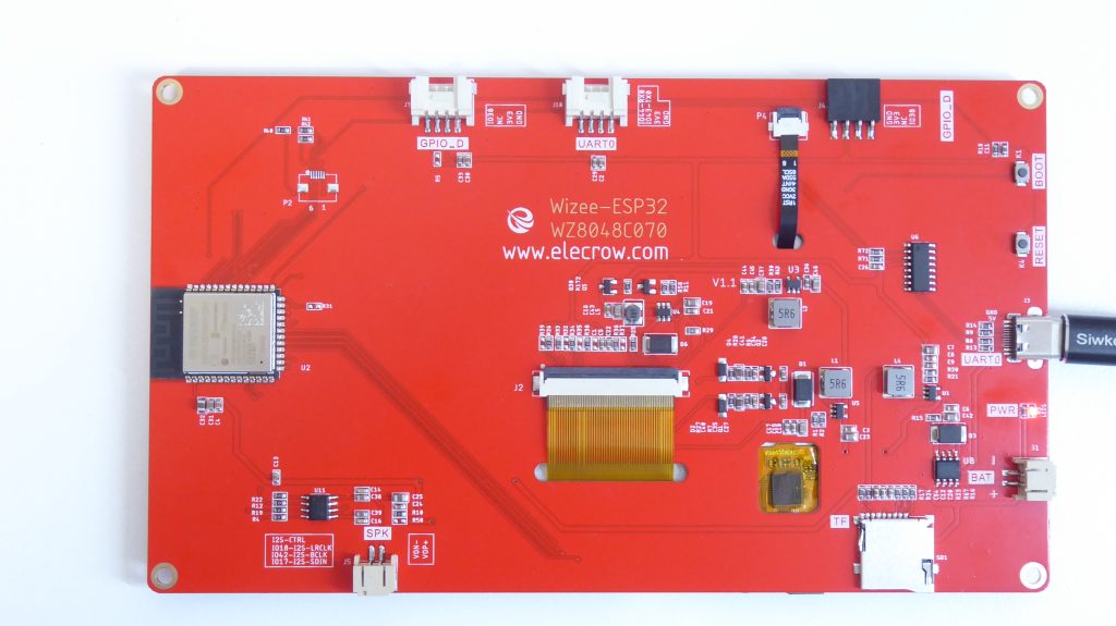
Power is via a single USB type C connector which also serves as the main USB port to connect to our development system, or as a separate USB port whilst the system is running.
The processor is an ESP32 S3 with a dual-core 32-bit LX6 microprocessor running at up to 240MHz, with integrated WiFi and Bluetooth wireless functions. This is teamed with 512K of fast SRAM backed up with 8MB of Pseudo Static RAM (PSRAM) running over a fast SPI channel. The ESP32 also has 4MB of built in flash storage, with an SPI connected SD card reader for mass data storage.
Around the board there are a number of IO connections.
We have 2 UART ports for serial communications along with a single GPIO output. This single GPIO output is probably the weakest area of the board so you won’t be able to connect lots of buttons and devices to the screen without resorting to one of the UART channels.
We also have a battery connector with battery management circuitry and an I2S driven speaker output so we can get some sound out of the board.
The touch panel on the screen is a capacitive touch device. It doesn’t have multipoint touch but is accurate and responsive making this unit ideal as a control panel for any of your projects.
Powering on the Display
When we first power on the display it will run a demo application showing its compatibility with the LVGL control panel software.
This is a very powerful user interface building tool that allows you to create professional level displays with all the modern features you’d expect such as scrolling panels, touch controls, graphic instruments, etc. These interfaces can be created using a free for personal use version of the development software.
I’m not going to go into the use of this tool in this video but it is well worth a look at if you want to put a great user interface on your project. I’ll probably cover this is a video later.
But for this video I want to look at the performance of the LCD panel as a standard display for our projects.
Driving the Display
The big difference between this unit and other ESP32 / LCD panel combos is the way it interfaces with the LCD panel.
There are a range of ways to attach an LCD panel to your microcontroller. SPI is a very common method where your ESP32 talks to an LCD controller chip using a serial communications protocol. Control commands and pixel data are sent over a simple 3 wire interface and you are able to create a very acceptable video output on smaller LCD panels. But the downside of this is that the serial channel is slow and transfers single bits of data at each clock cycle.
This method can restrict the resolution of the panel you can sensibly control with the microcontroller.
The RGB interface in this panel uses a 16 bit parallel data bus, which is the main reason why we don’t have many IO connections left, especially since we also need a few clock and control lines. With the driver chip using the standard 16 bit pixel colour data we therefore send 2 bytes or one pixel of information per clock cycle. The driver can display graphics on the screen using the standard range of primitive drawing commands, pixel, line, box, etc, or the display data can be sent over a screen area data dump, filling in an area of the LCD in one block. To do this we can use frame buffers in our code and then use DMA channels to perform the actual sending of the data over the interface. All of this gives us a very streamlined system for getting the display data to the LCD panel.
Running the interface at its maximum stable frequency of 15MHz gives us.
800 x 480 equates to 384K pixels per frame.
At 15MHz and sending a full screen dump, this gives us a theoretical frame rate of about 35 frames per second.
Driver Software
The RGB interface isn’t supported by all of the LCD driver libraries. In this video I’m going to be using the Lovyan GFX library, which is the one suggested by the Elecrow sample software. This sample software can be downloaded from the Elecrow website and includes examples for the screen, speaker, SD card and other system hardware.
To get the driver to work we need to set up a few class objects that implement the parts of the RGB interface. Again, this is detailed in both the Elecrow samples and the driver library code. I’ll briefly go through the setup here, but all of this will be available through the links at the bottom of this page.
Basic Driver Setup
The driver setup is a bit more involved for the RGB interface. But once you’ve got it going it’s identical for each of your projects with this device.
First we import the library and specify which version we want to work with
#define LGFX_USE_V1
#include <LovyanGFX.hpp>
#include <lgfx/v1/platforms/esp32s3/Panel_RGB.hpp>
#include <lgfx/v1/platforms/esp32s3/Bus_RGB.hpp>
We then need to create our own class inheriting from the main LGFX_Device class so that we can build our LCD panel model and embed it into the main library code.
class LGFX : public lgfx::LGFX_Device {
public:
  // Instances for the RGB bus and panel.
  lgfx::Bus_RGB     _bus_instance;
  lgfx::Panel_RGB   _panel_instance;
  lgfx::Light_PWM   _light_instance;

  // Constructor for the LGFX class.
  LGFX(void) {
We need to instantiate three objects to interface with the hardware.
The Panel object models the LCD panel itself along with some parameters such as width and height.
The Bus class sets up the hardware interface to the panel and defines the pinout, bus speed and display timing.
Finally the Light class allows provides brightness control for the LED backlight.
The Bus and Light objects are then embedded into the Panel object which is then set as the main panel in the library code so that it can use the main class methods to drive the display.
After this setup our code should be able to draw to the LCD panel.
In the test sketch we’re just getting it to fill the screen with a solid colour and then pause before changing colour.
So with our screen working we can move on to testing its performance.
Timing the Screen Filling Routine
In this code we’re again using the lcd.fillScreen method to fill the screen with a random colour, but we’re timing how long it takes for that function to complete. This method will send a full screen of pixel data to the panel as a single block write command so should give us the maximum full screen frame update rate achievable.
As you can see from the code running this takes about 33000us to complete which pretty much gives us our 30 frames per second maximum data rate.
This means that we should be able to animate our display with complete frame updates rather than having to delete and overwrite screen objects.
So let’s add some animation.
Frame Blanking Bouncing Boxes
In this example we’re going to bounce a number of boxes around the screen, clearing the display between each frame update. So the basic algorithm is to update the model positions of the boxes, then clear the screen, render the boxes and repeat.
As you can see this works and we do maintain a great frame rate. But with all the screen objects being draw in real time we get some strange timing effects where areas of the screen will disappear.
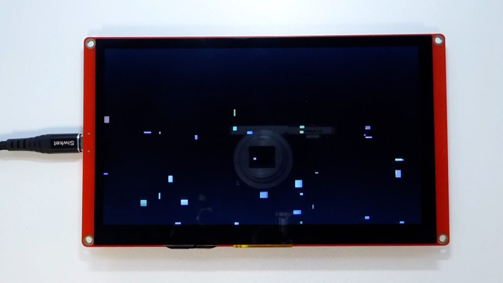
I think this is down to our eyes catching the LCD panel in various states of update. The display is continuously being changed with complete screen wipes taking up most of the display time.
We need to keep the full frame in view for a short time to let our eyes see it as a whole image. So we can add a short delay after the frame update is complete and this does now give us a correct and reasonably stable display, but of course we are now artificially slowing down the frame rate. As you can see from the display we do still see the frame being built object by object with the clear screen causing the flicker effect.
Having said that if your display does not need to update quickly and you’re refreshing dials and data at about 10fps, then you could use this technique.
So this gives you a very simple way of creating a full screen control panel with very easy updating code.
Using a Frame Buffer
The next step is to use a memory based frame buffer where we keep a representation of the screen in system memory, do all of our rending onto that before and then send the pixel data as a single update to the LCD panel. This should remove the flicker effect and the strange persistence of vision errors.
The Lovyan library has a LGFX_Sprite class that will do this for us. This class defines a block of screen memory that you can size to whatever screen dimensions you want that can then be rendered anywhere on the screen using a single block write. So we can create a sprite that is the full screen size, draw onto it and then display it so that it covers the whole panel.
In this demo that’s exactly what we’re doing.
![]()
As you can see we now get a correctly animated display, but we’ve lost a bit of speed in handling the sprite memory. The extra overhead of translating the sprite memory version onto the screen has taken our frame rate down to about 15 frames per second, doubling the time taken to generate a single frame.
But this method does allow us to have complicated drawing routines that won’t build up in front of the user as each element is drawn. We can do all the rendering off screen and then show the finished frame as one single screen update.
Optimising the Frame Rendering
If we take a closer look at our display and focus on a small region of the screen you can see that the majority of the screen pixels don’t change between frames. This means that a lot of the screen data we’re sending for each frame update is simply wasted time.
What we should be doing is looking for pixel changes between frames and only sending those over to the screen. This way we may only have to send perhaps 10% of the screen pixels over the RGB interface so we can greatly increase our frame rate.
To do this we now need to double buffer our display. This will let us have one buffer representing what’s currently on the screen, i.e. the last rendered frame, and one buffer with the newly generated frame. We can then scan the differences between the frames row by row and only send over the changed pixels.
This code does this in a new diffDraw function.
static void diffDraw(LGFX_Sprite* sp0, LGFX_Sprite* sp1)

{

  union

  {

    std::uint32_t* s32;

    std::uint8_t* s;

  };

  union

  {

    std::uint32_t* p32;

    std::uint8_t* p;

  };

  s32 = (std::uint32_t*)sp0->getBuffer();

  p32 = (std::uint32_t*)sp1->getBuffer();

  auto width  = sp0->width();

  auto height = sp0->height();

  auto w32 = (width+3) >> 2;

  std::int32_t y = 0;

  do

  {

    std::int32_t x32 = 0;

    do

    {

      while (s32[x32] == p32[x32] && ++x32 < w32);

      if (x32 == w32) break;

      std::int32_t xs = x32 << 2;

      while (s[xs] == p[xs]) ++xs;

      while (++x32 < w32 && s32[x32] != p32[x32]);

      std::int32_t xe = (x32 << 2) - 1;

      if (xe >= width) xe = width - 1;

      while (s[xe] == p[xe]) --xe;

      lcd.pushImage(xs, y, xe - xs + 1, 1, &s[xs]);

    } while (x32 < w32);

    s32 += w32;

    p32 += w32;

  } while (++y < height);

  lcd.display();

}
Here we’re using two sprite objects and alternating which one becomes the current and new frame.
When it’s time to update the display we look at the pixel data for each sprite going allow each row of pixels. If the pixels are the same we skip them. As soon as we find a difference we mark the start column and then work along until the pixel data matches again. This gives us a strip of altered pixels which we then send to the screen as one block.
The process then repeats itself.
If we look at the results we can get our frame rate back up to the 30fps we had initially, but this time with a nice steady display.
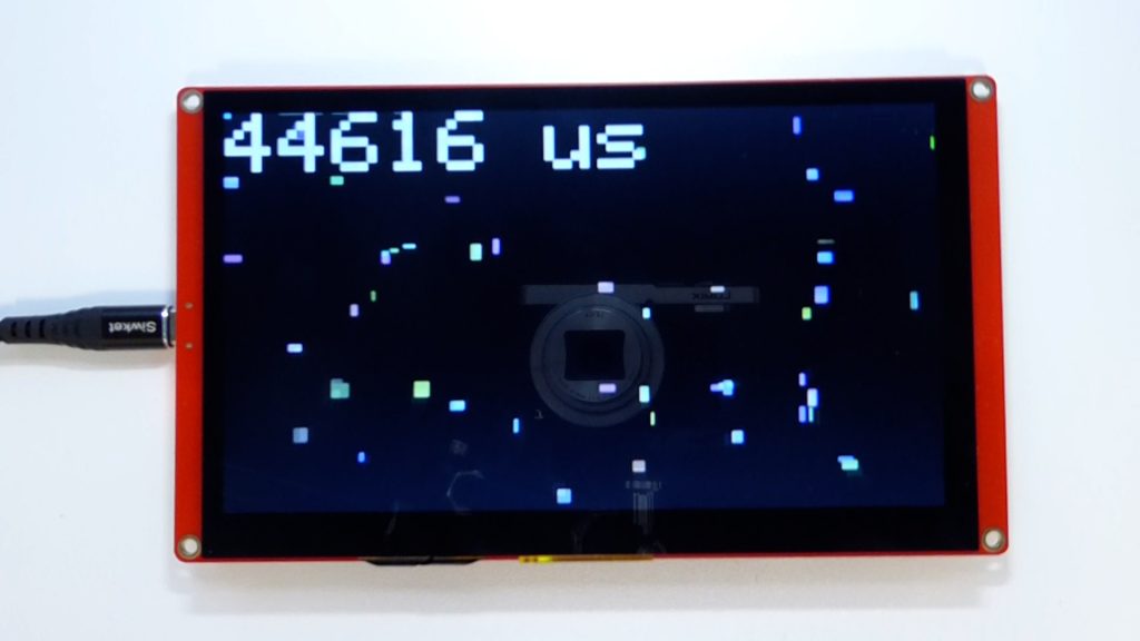
The difference routine we’ve used here is very basic. It relies on there being longer strips of either unchanged or changed pixels. If the screen display gets very complex it may end up increasing the frame drawing time rather than improving it. But in general this will work fine as most displays do contain large areas where nothing much is happening, even in games coding.
So this leads us to the final demo which is actually taken from the Lovyan examples.
Bouncing Circles Demo
This code uses the double buffered display driver, but uses the dual processors of the ESP32 to share the processing load of modelling the balls and updating the screen. Each ball’s physics is being modelled with proper collision detection and reactions between the objects. There is also a background grid being drawn per frame to add some interest to the display.
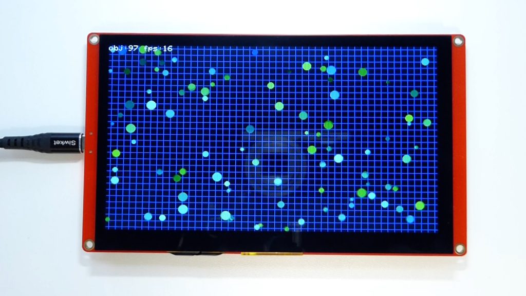
As you can see the initial frame rate of around 20fps drops off as the processing load to calculate the ball models increases. But I’m really showing it here as an example of what can be achieved with our trusty ESP32 and the RGB interface on the Elecrow display.
If we were to try to run a control panel or even some games code I think this display would cope fantastically well.
Conclusion
That that wraps it up for this video.
I’ve been really impressed at the speed and quality of the 7in display and how it opens the ESP32 up to a larger LCD unit whilst keeping the display driver running at a usable frame rate.
It will be great to look further into the LVGL library which uses a lot of the techniques we’ve discussed to allow the system to run a full screen, touch enabled user interface. But that will be for another video.
Code Downloads
Please use the following GitHub repo to download the Arduino IDE sketch files.

