Raspberry Pi Zero Sound Output – Add Analog Sound Through a Headphone Socket and Speaker
27th May 2021
How to Overclock Your Raspberry Pi – Squeeze Out More Processing Power
3rd June 2021Raspberry Pi I2S Sound – Add Digital Sound Output to Your Raspberry Pi
(This page is part of the Raspberry Pi Handheld Games Console series. Please click here for the full project.)
There are several ways of getting sound out of your Raspberry Pi and Raspberry Pi Zero. In a previous episode I showed you how to get analogue audio out of the Raspberry Pi Zero using the alternative functions on some of the GPIO pins. In this tutorial I’ll show you how to use the I2S digital audio signal to add sound to our handheld games console.
What Is an I2S Signal?
I2S stands for Inter IC Sound. It was designed as a way of sending sound information between parts of the circuit board as a digital data stream avoiding all the noise issues associated with analogue signals. To send the sound signal you need a minimum of three signal wires. One wire acts as a bit clock to synchronise the individual bits of data, one acts as a left/right clock to specify whether the data being sent is for the left or right channels, and a data wire for the digital data.
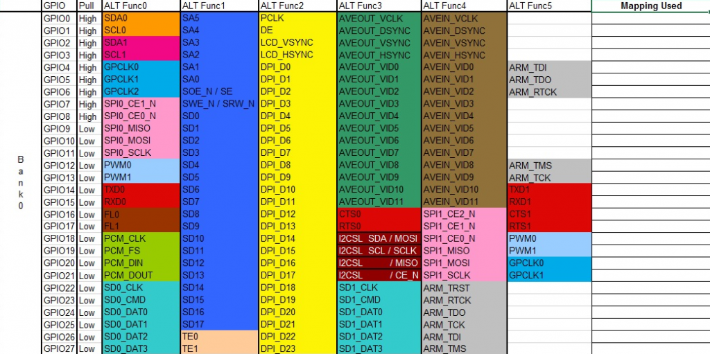
On all Raspberry Pi’s the GPIO header provides these data signals as ALT0 functions on its GPIO pins
GPIO18 = Bit Clock
GPIO19 = Left Right Clock
GPIO20 = Data In
GPIO21 = Data Out
For our setup we don’t need the Data In connection as the Raspberry Pi will only be sending sound data, not receiving it.
Hardware Needed for I2S Sound
The signals coming out for GPIO pins are the digital data and clock signals. We need some external hardware to convert these to sound.
The first part of our circuit needs to be an I2S Digital to Analogue Converter (DAC) which can decode the I2S signal and convert it to an analogue, stereo sound signal. As we want to be able to have both a headphone output and a loudspeaker, we’ll need this first conversion stage to provide a signal suitable for our headphones rather than a fully amplified signal designed for a loudspeaker.
Once we have this line level output we can then feed it to a headphone jack socket and then into an audio amplifier before finally sending it to our speaker.
The circuit I’ve used for testing the system is shown below.
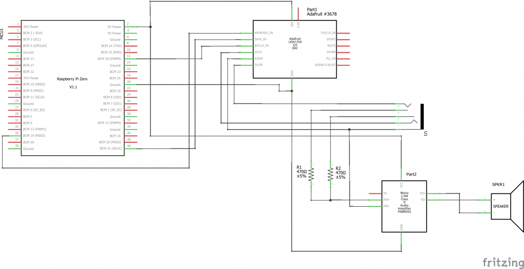
I’ve used two ready-made modules from AdaFruit for the DAC and amplifier. The output from the DAC is fed into the headphone socket as it can drive headphones directly. Although the module has its own headphone socket this does not provide a switched output to the amplifier. I’m using a separate headphone socket with a switched output. This output is then fed through 2 resistors to combine the stereo signal into a single mono channel. This is then fed into the mono amplifier which can then power the speakers.
This arrangement on the headphone socket means that when we plug in a set of headphones the amplifier signal is disconnected so the speaker falls silent.
Building the Circuit
For the testing phase I’m building the circuit on breadboard. Once I’ve got everything working, I’ll then design a custom PCB to put everything onto one board.
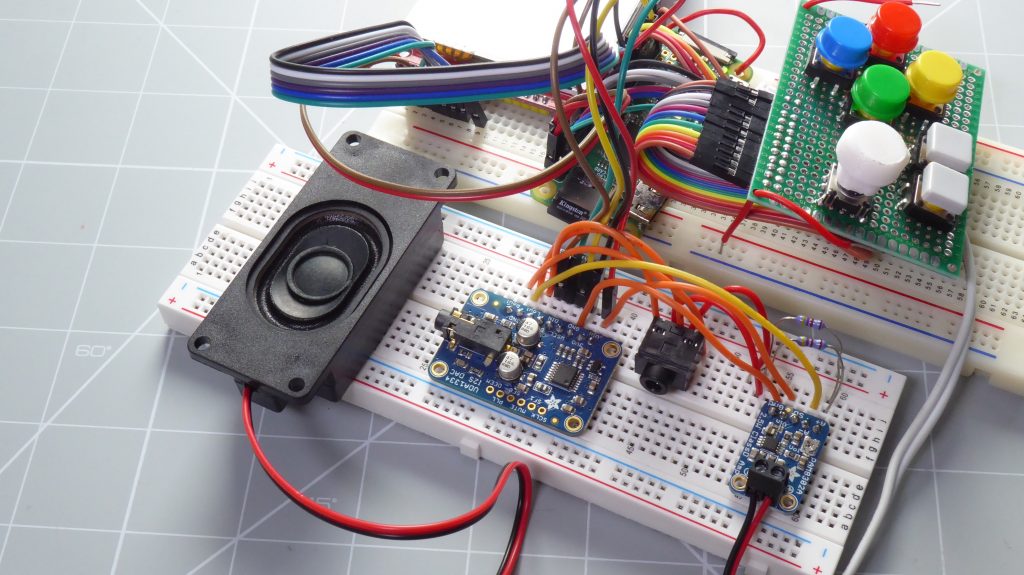
Software Setup
By default, the Raspberry Pi does not output the I2S signal. We’ll need to configure the board to generate I2S and send this out via the GPIO pins.
The following setup is taken from the Adafruit tutorial for the UDA1334A board at
https://learn.adafruit.com/adafruit-i2s-stereo-decoder-uda1334a/raspberry-pi-usage
I had a couple of problems using this setup procedure so please have a read through these tips to get things working as quickly as possible.
The main issue I found was that the fast installation script provided on the above page caused a permissions issue with some of the software. Once installed the Alsa sound module needed to be run with raised permissions. You had to use sudo for the commands to give it access to some of the files required to work. When RetroPie tried to access the sound system it was then unable to run under raised permissions so the sound failed.
The only way around this was to completely rebuild the RetroPie installation and install the sound script first before adding the LCD or GPIO controller software. Even then it was a bit twitchy.
My recommendation is to use the manual installation and to do it on top of a fresh RetroPie setup if possible. Adding the LCD and GPIO controller software first works fine but switching over from an analogue sound setup to I2S again seemed to be an issue – at least during my tests!
Manual Software Setup
Remove Any Blockages to I2S Sound
We first need to make sure that the analogue sound hardware and drivers are disabled.
The first file we need to check is, /etc/modprobe.d/raspi-blacklist.conf, which can contain a list of software modules that the system will ignore.
sudo nano /etc/modprobe.d/raspi-blacklist.conf
If the file is empty just use ctrl+X to exit. If you see any of the following lines just comment them out by putting a # in front of the line.
blacklist i2c-bcm2708
blacklist snd-soc-pcm512x
blacklist snd-soc-wm8804
Then use ctrl+X , Y to save the file.
We then need to disable the headphone analogue sound output software module.
sudo nano /etc/modules
The file will have a coupe of modules listed (if you’re using RetroPie). The sound module is snd_bcm2835. If you see this listed just comment it out by putting a # at the start of the line.
Again ctrl+X, Y to save and exit.
Configure the I2S Sound Software
Our system will use the Alsa-project software to drive the I2S signal and sound system. This is usually installed by default but we can use the command below to make sure it’s up to date.
sudo apt-get install alsa-utils
We next need to create a configuration file for the Alsa sound system. This will define a number of audio devices and how they should be set up so that the sound system can then use them to generate and output the sound signals.
sudo nano /etc/asound.conf
Paste the following code into this file.
pcm.speakerbonnet {
   type hw card 0
}

pcm.dmixer {
   type dmix
   ipc_key 1024
   ipc_perm 0666
   slave {
     pcm "speakerbonnet"
     period_time 0
     period_size 1024
     buffer_size 8192
     rate 44100
     channels 2
   }
}

ctl.dmixer {
    type hw card 0
}

pcm.softvol {
    type softvol
    slave.pcm "dmixer"
    control.name "PCM"
    control.card 0
}

ctl.softvol {
    type hw card 0
}

pcm.!default {
    type             plug
    slave.pcm       "softvol"
}
This basically sets up a PCM audio device along with a mixer device to allow us to adjust the volume in software.
The final step is to edit the config.txt file to load the device tree overlays at start up.
sudo nano /boot/config.txt
First look for the line
dtparam=audio=on
This turns on the standard headphone outputs so we need to disable it by commenting out this line – just put a # at the start of the line.
Then at the bottom of the file we need to add the I2S overlays.
dtoverlay=hifiberry-dac
dtoverlay=i2s-mmap
Ctrl+X, Y to save and exit and then we need to reboot the Raspberry Pi to get all the changes loaded.
Testing the I2S sound Output
With the hardware connected and the software installed it’s time to test!
The speaker-test script lets you quickly test the setup.
speaker-test -c2
is the simplest test where white noise (a hissing sound) is played though the left and right channels one after the other. If you can hear this on your headphones and speaker it means it’s all working.
Next, we can try playing a simple WAV file.
speaker-test -c2 --test=wav -w /usr/share/sounds/alsa/Front_Center.wav
This should give you a lady saving, “Front, Centre” repeatedly.
If that’s all working, we’re almost ready to go.
Adjusting the Volume
In the circuit diagram shown above I didn’t add a volume control – I’ll probably add that in when designing the final circuit. Volume adjustments will have to be made in the software setup. The Alsa sound package has a mixer script.
alsamixer
This should bring up a screen with a volume bar. You can use the up and down arrows to control the sound level. Once you’ve got that at the right level, you’ll need to save the setting by running this command.
sudo alsactl store
Sound Output in RetroPie
If everything is working OK it’s time to set up RetroPie. Reboot the system and go into the RetroPie settings (press the start button). Go to Audio Settings.
For AUDIO CARD we need to select DEFAULT.
For AUDIO DEVICE select PCM.
For OMX PLAYER AUDIO DEVICE select BOTH.
Set your volume to your own preference.
Once you’ve set these values you should be good to go.
Boot up a game and enjoy the full sound experience!
Next Step
In this Raspberry Pi Zero, handheld, retro games console project we’ve now got the emulator running on the Raspberry Pi, a full speed screen running on a cheap SPI LCD screen, our own GPIO connected game controller and finally a digital sound output through headphones and speaker.
This current setup gives a fully playable system, but it needs a USB power supply.
The next step is to add the option for both USB power, and battery power, with the built-in batteries being recharged by the same USB connection.

