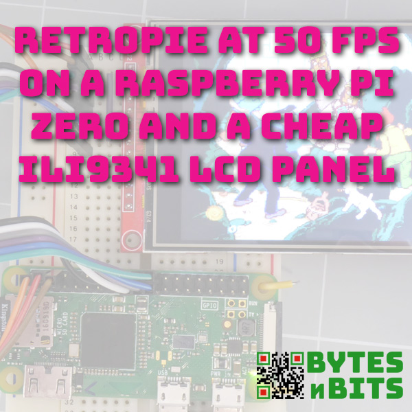
Fastest FPS on Your Raspberry Pi SPI LCD Screen – Make RetroPie playable on a cheap LCD panel
28th April 2021
Space Commander Overview – Learn to Code Your Own Games
9th May 2021RetroPie on a Raspberry Pi Zero at 50FPS on an SPI LCD Screen With ILI9341 Driver
(This page is part of the Raspberry Pi Handheld Games Console series. Please click here for the full project.)
To build a handheld Raspberry Pi powered gaming console we are going to need an LCD screen. There is a wide range of LCD panels available for the Raspberry Pi ranging in price, size and method of connection.
Keeping the Cost down
In this project I’m aiming to keep the cost as low as possible while still keeping good enough quality to give us a great gaming experience.
The best option to get a full 60 frames per second video output is to use an HDMI or DSI connected LCD panel. These simply plug into the correct socket on the Raspberry Pi and that’s all you need to do. But these panels tend to cost £50 or more for a 3 inch or bigger screen.
A cheaper option is to use a serial SPI connected LCD panel. You’ll pick up a 3 inch version of this type for under £10. The problem of course is that the serial channel gives a much slower frame rate than either the HDMI or DSI connections.
So in this part of the project were going to optimise our serial connection to give us a high frame rate on one of these very cheap LCD screens.
Getting the Raspberry Pi Set up
For this project I’ll be using the Raspberry Pi Zero. We’ll need to get this set up with RetroPie installed and the ability to access the terminal screen on the Raspberry Pi. In the video I show you how to connect remotely using SSH, but you can use a keyboard and screen if you prefer.
Connecting the LCD Screen to The Raspberry Pi
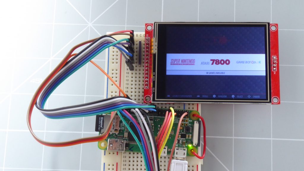
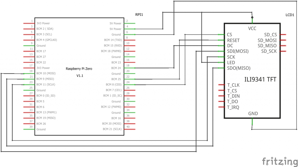
Quite a few LCD panels plug directly onto the GPIO connector on your Raspberry Pi. This obviously makes it very easy to connect the screen but makes it harder to use the rest of the GPIO pins. So I’ll be using a generic, ILI9341 driven LCD panel.
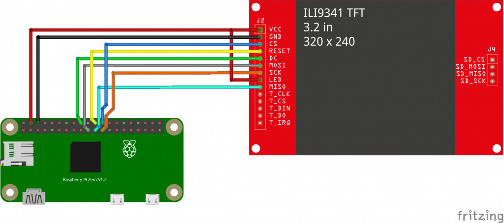
This does mean that will need to work out how to connect it to the GPIO pins.
If you look at the Raspberry Pi pinout you’ll find a number of pins assigned to the SPI connection.
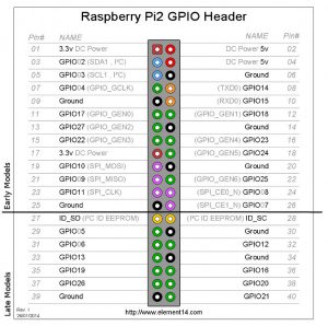
GPIO9, 10 and 11 act as MISO, MOSI and CLK. GPIO8 is a default chip enable (chip select). So for our generic LCD panel we just need to find pins for RESET and DC. To make things easy I’ve copied the connections for a WaveShare compatible screen which uses GPIO24 for the DC connection and GPIO25 for RESET.
Installing the Driver Software
To get the fastest frame rate possible we’re going to use the FBCP-ILI9341 driver software that I used in a previous video.
Installing the FBCP-ILI9341 Driver
I’ll repeat the steps here to keep everything in one place.
Removing Any Existing Drivers
Before we install the new driver, we have to make sure that any existing drivers are removed. If we don’t the two will interfere with each other and our screen won’t work.
Two files control the drivers and services used by the LCD screen. The first is /boot/config/.txt. This file allows you to turn on various hardware services unload the LCD driver software. If you’re using RetroPie use the menu button and quit Emulation Station or if you’re just on a standard Raspberry Pi open a terminal window.
sudo nano /boot/config.txt
Typing in the above command will open the file for editing. We first need to make sure that the standard SPI drivers aren’t loaded. Look for the line
dtparam=spi=on
and comment it out by putting a # in front of it. Next we need to remove the LCD and touch panel drivers. Look for lines like
dtoverlay=waveshare32a
or something relevant to your LCD panel. Again, that out using a # symbol. Touch panel lines will look something like
dtoverlay=ads7846
or mention
penirq=
somewhere in the command. Again, comment these out.
Once you’ve edited this file press ctrl X to quit nano, Y to tell it to save the file and enter to accept the filename.
The second file we need to edit is /etc/rc.local which controls some of the start-up command options on the Raspberry Pi. Look for a command that mentions fbcp and comment that out. It may well have done & at the end of the line and that needs to be commented out.
change
fbcp &
to
#fbcp &
You’ll now need to reboot the Raspberry Pi but make sure you’ve either got it connected to a monitor or that you’re able to use SSH to remotely access the device. We’ll need to make some more changes using the Linux terminal.
Installing the FBCP-ILI9341 Software
The software is stored as a GIT repository. Will first need to download the code onto our Raspberry Pi. Make sure you are in your home directory
cd ~
and then clone the software repository with the following command.
git clone https://github.com/juj/fbcp-ili9341.git
This should copy all the files into a folder in your home directory. We then need to make sure that the cmake application is installed on your computer.
sudo apt-get install cmake
It’s probably already installed but this will make sure it is and that it’s up to date. We are now ready to build a compile the software. Change directory to the project folder.
cd fbcp-ili9341
We then need to create a folder where we’ll build the actual software. It doesn’t matter what you call this directory but the convention is to call build.
mkdir build
Then change directory into this folder.
cd build
We now need to use the cmake application to create the build files with the correct options for our particular LCD screen.
cmake [options] ..
We’ll discuss what options you need to add but notice that there are two full stops at the end of the line. This ensures that our project is built using the files in the folder above where we are. Once this command is finished we need to compile the software.
make -j
This will create a file fbcp-ili9341 in our build directory which is the compiled driver for our LCD screen. We can check that works by typing the following command.
sudo ./fbcp-ili9341
You should see your monitor display mimicked on your LCD screen. Just press ctrl C to exit the driver.
Selecting the Make Options
As I mentioned above we need to work out what make options we need to get this LCD panel working with our Raspberry Pi. As we are no longer using one of the standard screens will need to use the generic options to tell the software about our screen.
The first option we need to set tells the software what driver chip our LCD screen uses. You’ll usually find this in the datasheet for your particular LCD panel. Most panels with a 320 x 240 pixel resolution will use the ILI9341 chipset, but do make sure you check yours first. If you look in the README file in the repository you’ll see a list of valid driver chips and the options you need to set for each.
-DILI9341=ON: If you are running on any other generic ILI9341 display, or on Waveshare32b display that is standalone and not on the FreeplayTech CM3/Zero device, pass this flag.
-DILI9340=ON: If you have a ILI9340 display, pass this directive. ILI9340 and ILI9341 chipsets are very similar, but ILI9340 doesn’t support all of the features on ILI9341 and they will be disabled or downgraded.
-DHX8357D=ON: If you have a HX8357D display, pass this directive.
-DSSD1351=ON: If you have a SSD1351 OLED display, use this.
-DST7735R=ON: If you have a ST7735R display, use this.
-DST7789=ON: If you have a ST7789 display, use this.
-DST7789VW=ON: If you have a ST7789VW display, use this.
-DST7735S=ON: If you have a ST7735S display, use this.
-DILI9486=ON: If you have a ILI9486 display, pass this directive.
-DILI9486L=ON: If you have a ILI9486L display, pass this directive. Note that ILI9486 and ILI9486L are quite different, mutually incompatible controller chips, so be careful here identifying which one you have. (or just try both, should not break if you misidentified)
-DILI9488=ON: If you have a ILI9488 display, pass this directive.
-DMPI3501=ON: If specified, targets a display with MPI3501 display controller.
So we’ll need to set the option to specify an ILI9341 board.
-DILI9341=ON
We then need to tell the software which pins we’ve used to connect to the Raspberry Pi. The driver assumes that were using SPI channel 0 and the CE0 chip enable pin. After that we need to specify the RESET and DC pins. Note that the pin numbers need to be BCM numbers rather than the actual pin numbers on the connector. For example to specify our RESET pin which is connected to GPIO25 on pin number 22, we use 25.
-DGPIO_TFT_DATA_CONTROL=24

-DGPIO_TFT_RESET_PIN=25
Finally we need to set the SPI channel frequency. This is achieved by specifying a divisor. The BCM chip inside the Raspberry Pi runs at the default rate of 400 MHz. To get the SPI channel frequency we divide this by the number we specify. This divisor must be an even number. To begin with we’ll choose a larger divisor to give us a slower SPI frequency to make sure that we got everything connected correctly. Once we got the screen working we can start to play with this number to get our higher frame rates.
-DSPI_BUS_CLOCK_DIVISOR=30
This will initially set our SPI frequency to 13.3 MHz, a very safe frequency.
So the full cmake command we need to create the correct build files will be…
cmake -DILI9341=ON -DGPIO_TFT_DATA_CONTROL=24 -DGPIO_TFT_RESET_PIN=25 -DSPI_BUS_CLOCK_DIVISOR=30 ..
If you go through the installation process detailed above and activate the driver with the command
sudo ./fbcp-ili9341
you’ll hopefully get the Raspberry Pi output displaying on your LCD screen.
Optimising the Frame Rate
The make command above also instructs the driver to display its statistic screen. This lets you see how well the drivers performing and what frames per second is giving you. The frames per second value is the number in the top left corner.
We now need to tune our divisor value to give us the best frame rate without corrupting the display.
To do this we have two exit the driver software, delete the previous build, compile a new build with the new divisor setting and then run this version of the driver software.
cd ~

cd fbcp-ili9341

rm -r build
Then follow the previous build process from the point where you make the build folder.
50 Frames per Second?
With an ILI9341 driver you should be able to get the divisor down to about 6. This gives an SPI frequency of 66.7 MHz which should allow your screen to reliably get to about 50 frames per second.
Removing the Statistics Screen
Once you’ve got the screen frame rate optimised as best you can we just need to remove the statistics panel. You’ll have to remake the driver software again with one extra make option.
-DSTATISTICS=0
Flipping the Screen
Depending on how you’ve mounted your LCD panel you might find that it’s upside down. To flip it round you need to add the following build option.
-DDISPLAY_ROTATE_180_DEGREES=ON
My Complete Build Command
Just for reference my completed build command ended up as.
cmake -DILI9341=ON -DGPIO_TFT_DATA_CONTROL=24 -DGPIO_TFT_RESET_PIN=25 -DSPI_BUS_CLOCK_DIVISOR=6 -DSTATISTICS=0 -DDISPLAY_ROTATE_180_DEGREES=ON ..
Automatically Starting the Driver When the Raspberry Pi Boots
To get the driver to automatically start when the Raspberry Pi boots up we need to add a command to your rc.local file.
sudo nano /etc/rc.local
Just before the exit 0 line, you need to add the following command.
sudo /home/pi/fbcp-ili9341/build/fbcp-ili9341 &
If you now reboot the Raspberry Pi you should find that your LCD panel starts up automatically. It does take a bit of time during the boot sequence before the LCD panel is activated so don’t worry that you don’t see the normal Raspberry Pi splash screen on the LCD.
Matching Your HDMI Resolution to Your LCD Screen Resolution
One final optimisation we can make is to match our HDMI resolution to our LCD screen resolution.
The driver software works by copying what’s being displayed on the HDMI output and then resizing it for the LCD screen. By resizing the HDMI resolution Linux will optimise the display for the lower resolution. When the driver software copies this to the LCD screen it won’t have to resize the output which should make the display slightly clearer, especially for smaller text sizes.
To do this will need to edit the config.txt file in the boot folder of the Raspberry Pi.
sudo nano /boot/config.txt
First we need to make sure that the HDMI output is forced on. Since there is no screen attached to the Raspberry Pi it might decide to use the composite video output instead of HDMI.
Find the following line and uncommented by removing the # symbol, or add the line at the bottom of the file if it’s not there.
hdmi_force_hotplug=1
We want to disable over scanning so that there are no black borders showing around the screen. Again either uncomment or add the following line.
disable_overscan=1
We then need to set a custom display mode for the HDMI output and make sure that the HDMI signal is forced on.
hdmi_cvt=320 240 60 5

hdmi_group=2

hdmi_mode=87

hdmi_drive=2
In the above code the first two numbers in the hdmi_cvt command specify the pixel dimensions of your LCD screen.
For more details on the various parameters we can use in the config.txt file please see the Raspberry Pi documentation at
https://www.raspberrypi.org/documentation/configuration/config-txt/
The Next Step
Now that we’ve got our LCD screen working correctly and that a good frame rate will need to move on to the next steps in building up our handheld Raspberry Pi retro games console. Please make sure you check out the other tutorials in this series by visiting the main Raspberry Pi retro games console page.

